


Control Panel Installation
151209 4-23
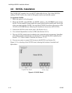
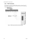
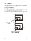
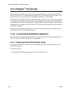
4.8.3 LED Wiring
There are four 12-pin connectors on the 5880 board for connecting LEDs. Each LED gets its
power from Pin 11. Internal resistors are sized so that there is approximately 10 mA of current
for each LED, no series resistors are required. LED outputs can be mapped to output circuits.
See Section 6 for programming details.
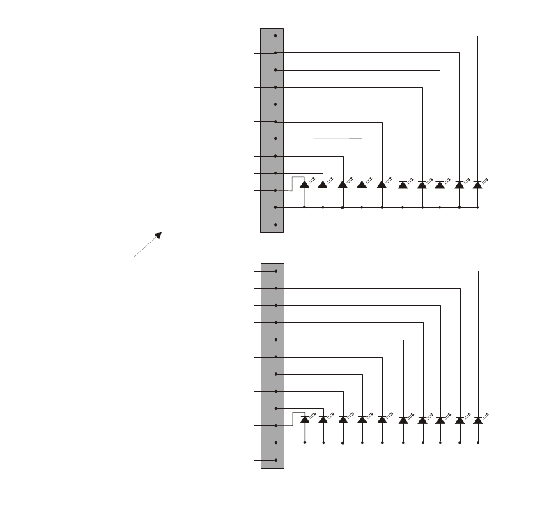
Wire the LEDs as shown in Figure 4-22.
On connector P1, Pin 12 is an open collector output for controlling a PZT. If used, the 5880
PZT will match the PZT pattern of the on-board (or 5860) annunciator.
Note: The circuit connected to “Open Collector Output” (last pin on P1) must be current limited so that no more
than 100 mA of current is allowed to flow into the open collector transistor.
Figure 4-22 5880 Board Layout
11
20
12
13
14
15
16
17
18
19
LED Power
no connection
Anode
Cathode
LEDs
P2
5880 LED Outputs
1
10
2
3
4
5
6
7
8
9
LED Power
Programmable Open Collector Output
Not mappable.
Matches PZT pattern
on on-board
annunciator
Anode
Cathode
LEDs
P1
Connectors P3 and P4 wired same as P2.