


Before You Begin Installing
151209 3-3
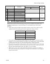
3.4 Wiring Specifications
Induced noise (transfer of electrical energy from one wire to another) can interfere with
telephone communication or cause false alarms. To avoid induced noise, follow these
guidelines:
• Isolate input wiring from high current output and power wiring. Do not pull one multi-
conductor cable for the entire panel. Instead, separate the wiring as follows:
• Do not pull wires from different groups through the same conduit. If you must run them
together, do so for as short a distance as possible or use shielded cable. Connect the shield
to earth ground at the panel. You must route high and low voltages separately.
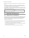
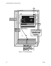
• Route the wiring around the inside perimeter of the cabinet. It should not cross the circuit
board where it could induce noise into the sensitive microelectronics or pick up unwanted
RF noise from the high speed circuits. See Figure 3-1 for an example.
• High frequency noise, such as that produced by the inductive reactance of a speaker or
bell, can also be reduced by running the wire through ferrite shield beads or by wrapping it
around a ferrite toroid.
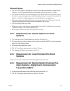
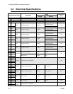
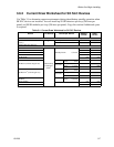
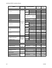
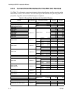
37 Ring Phone Line 1 Telco Ring
N/A 0Ω
38 Tip Phone Line 1 Telco Tip
39 Ring Phone Line 1 Premises Ring
40 Tip Phone Line 1 Premises Tip
41 Ring Phone Line 2 Telco Ring
N/A 0Ω
42 Tip Phone Line 2 Telco Tip
43 Ring Phone Line 2 Premises Ring
44 Tip Phone Line 2 Premises Tip
45 SC- SLC Programming Terminal ( - ) 32 VDC 150 mA
0Ω
46 SC+ SLC Programming Terminal ( + ) 32 VDC 150 mA
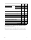
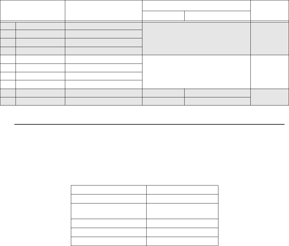
High voltage AC power, Terminals 1-3
SLC loops Terminals 33-36
Audio input/output Phone line circuits, Terminals
37-44
Notification circuits Terminals 4-15
SBUS Terminals 16-23
Relay circuits Terminals 24-32
Terminal # and Label Description
Rating
Earth Ground
Faults
Voltage Current