


IntelliKnight 5820XL Installation Manual
10-2 151209
10.2.1
To ensure proper and reliable operation, it is recommended that system inspection and testing
be scheduled monthly or as required by national and/or local fire codes. Testing should be
done by a qualified services representative if a malfunction is encountered.
Before testing:
1) Notify the fire department and/or central alarm receiving station if an alarm condition is
transmitted.
2) Notify facility personnel of a test so that alarm sounding devices are ignored during the test
period.
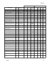
SLC devices are not being recognized
(trouble message "Missing" displays on
the annunciator).
Check that SLC loop impedance is within the required range.
To measure impedance, use the following procedure.
1. Disconnect both wires from the terminal block at the panel (SLC devices
can remain connected).
2. Measure the impedance from positive to negative and from negative to
positive. Both measurements should be greater than 500 K ohms. If the
installation uses T-taps, test each T-tap individually.
3. Temporarily connect the positive wire to the negative wire of the SLC loop
at the point farthest from the panel (SLC devices can remain connected).
4. Measure the impedance from positive to negative and from negative to
positive. Both measurements must be less than 50 ohms.
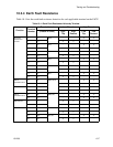
The panel indicates a ground fault trouble
condition (trouble message "GROUND
FAULT" displays).
An earth ground fault occurs when the panel senses an unexpected flow of
current from one or more of its terminals to the earth connection (Terminal 2).
Isolate the wiring that is causing the fault by removing wiring connections
one at a time until the earth fault is no longer present. Pause at least five
seconds after removing a wire before removing the next one.
The panel will also go into ground fault if a computer is connected to the
panel via a serial cable attached to the panel’s 9-pin connector. This is a
correct method for on-site communication between a panel and a computer.
Ignore the ground fault message in this case. The trouble will clear
automatically when you disconnect the computer from the cable
5815XL module that has been physically
connected to the panel but is not being
recognized.
Check the status of the 5815XL green LED. If it flashes in the pattern .5 sec.
on / .5 sec. off, it is likely that the 5815XL has not been added to the system
through programming. JumpStart will add any 5815XLs connected to the
panel. If you have already run JumpStart, 5815XLs can be added manually
(see Section 7.3.2).
Check that the correct ID for the 5815XL module has been set through the
DIP switches. Assign ID#1 to the first 5815XL and ID#2 to the second
5815XL. See Section 4.10.1 for complete details.
If the wiring between the 5815XL and the panel is correct, measure the
voltage from 5815XL Terminal (+) to Terminal (-). Voltage should be in the
range 27.2-27.4V when AC power is present.
If the green LED is not flashing, the likely cause is incorrect wiring from
between the 5815XL and the panel. See Section 4.6.1 for wiring details.
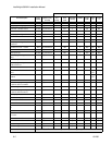
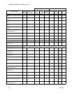
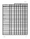
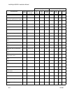
Problem Possible Cause / Suggested Actions