


Control Panel Installation
151209 4-5
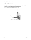
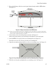
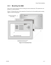
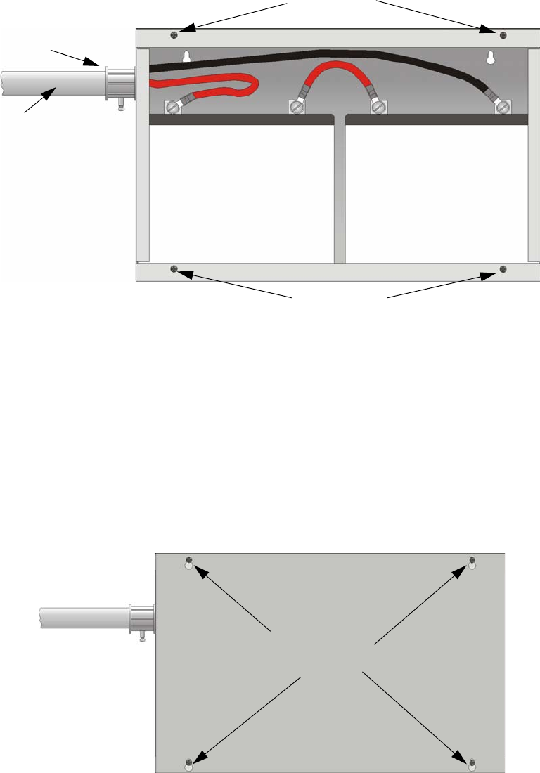
3. Run extended battery cable from control panel cabinet through conduit to RBB cabinet.
See Figure 4-5.
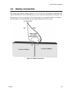
Figure 4-5 Battery Connections in the RBB Cabinet
Note: Figure 4-5 is an example of how the wire connections can be routed. However, any other cabinet knock-
outs (on either the main control panel or the RBB cabinet), that are not previously being used may be uti-
lized to connect conduit between the two cabinets.
4. Connect battery leads to the backup battery terminals. See Figure 4-5.
Observe the proper polarity to prevent damage to the batteries or the control panel.
5. Insert the RBB cover screws into the cover mounting holes (see Figure 4-5).
Screw the cover screw 3/4 of the way into the cover mounting hole.
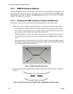
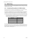
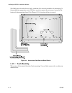
6. Align the cover plate mounting keyhole over the cover mounting screws. See Figure 4-6.
Figure 4-6 Cover Plate Mounting Keyholes and Cover Mounting Screws Alignment
7. Slide the cover into place and tighten the cover mounting screws. See Figure 4-6
Conduit
Conduit
Coupler
+
+
-
-
RBB Cabinet
Cover Screws
RBB Cabinet
Cover Screws
Cover Plate
Mounting Keyholes