


66
Step 4 — Make Duct Connections — Install all
ductwork to and from unit in accordance with all applicable
codes. Duct construction must allow unit to operate within duct
external static pressure limits as shown on job submittals. Units
designed to operate with ductwork may be damaged if operated
without intended ductwork attached.
Units provided with outside air should have some method
of low-temperature protection to prevent freeze-up.
Insulate ductwork as required. Use flexible connections to
minimize duct-to-unit alignment problems and noise transmis-
sion where specified.
Set unit markings for minimum clearance to combustible
materials and first 3 ft of ductwork. Install ductwork, accessory
grilles and plenums so that they do not restrict access to filter.
Cut openings for supply-air and return-air grilles, thermostats
and switch plates where specified on job drawings. Be careful
not to cut wires, piping or structural supports. Use a steel ther-
mostat shield ring to protect drywall from thermostat wiring
where applicable.
Step 5 — Frame and Finish Unit — Models 42SG,
SH and SJ have factory enclosures and may be finished with
normally accepted wall covering. However, drywall secured
with adhesive bonding alone is not recommended.
Use low-profile sheet metal panhead screws to secure
wallboard to unit frame.
Do not apply sheet metal screw or nails where they can pen-
etrate coil, riser pipes, or electrical junction box and raceways.
Do not secure wallboard to drain pan edges or to control
box enclosure. Condensate leaks or electrical shorts may result.
An alternate method of enclosing the unit is to frame one or
more sides with studding and apply the wall board to this fram-
ing. This method requires specific unit features and return ac-
cess panels when used on the return-air side of a unit. Units not
properly equipped will exhibit poor cooling and/or heating per-
formance and could experience excessive or premature compo-
nent failures.
Prevent sheetrock dust or other debris from settling on coil
fins, motor-blower assembly or other unit interior surfaces.
Return access and exposed cabinet units may be furnished
with a baked enamel finish. Small scratches in this finish may
be repaired with touch-up paint available from the factory.
Some colors of touch-up paint are available in aerosol contain-
ers and all touch-up paint is available in pint, quart, and gallon
cans.
To repaint the factory-baked enamel, the finish should be
prepared by light sanding with no. 280 grit sand paper or
no. 000 or no. 0000 fine steel wool. The surface may also be
wiped with a liquid surface etch cleaning product such as “No
Sand” or “Pasceo.” These items should be available at most
paint product stores. It should be noted that the more conscien-
tiously this preparation is done, the more effective it will be.
After this preparation is accomplished, the factory finish
should provide excellent adhesion for a variety of air-dried top
coats. Enamel will give a more durable, higher gloss finish,
while latex will not adhere as well and will give a dull, softer
finish. Top coats involving an exothermic chemical process be-
tween two components, such as epoxies and urethanes, should
be avoided.
Factory aerosol touch-up paint may require a number of
light “dust coats” to isolate the factory-baked enamel finish
from the quick drying touch-up paint.
CAUTION
Prevent dust and debris from settling in unit. If wall finish
or color is to be spray applied, cover all openings to pre-
vent spray from entering unit. Failure to do so could result
in the reduction of unit efficiency.
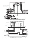
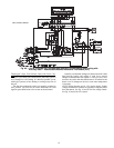
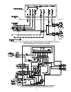
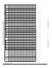
Fig. 68 — 42C,S,V (except VG), and 42D (600-1000 cfm) 4-Pipe Heating and Cooling —
Remote/Wall-Mounted Debonair
®
Thermostat (24-v)
G
THERMOSTAT #33CSSN2-FC
RG3Y1 W1 CG2 H2O CK1RSRS+5
QUICK CONNECT
REMOTE DEVICE BOX
NEC CLASS 2 WIRING
33ZCRLYBRD
G
G2/(W)
G3/(Y)
COM
FAN
(VALVE)
(COOL)
HI
(HEAT)
MED
LOW
TRANSFORMER
24
YEL
BLK
VALVE
BLK
Q/C
BLK
YEL
YEL
YEL
BLU
BLK
PUR
RED
ORG
BLK
BLOWER
MOTOR
COM
WHT
BLK H
BLU M
RED L
COOL
4
3
2
1
GROUND
EQUIPMENT
L1
L2 or N
*WHT
2
1
BLK
*WHT
BRN
BLK
1
HEAT
VALVE
BLK
Q/C
2
YEL
BRN
PUR
RED
BLU
BLK
YEL