


49
42C,D,V DRAIN CONNECTIONS — Install drain line in
accordance with all applicable codes. A continuous pitch of
1 in. per 10 ft of condensate drain line run is necessary for
adequate condensate drainage. Insulate the drain line to
prevent sweating. Extend the drain line straight from the drain
pan before making any turns. The installer must provide proper
support for the drain line to prevent undue stress on the
auxiliary drain pan.
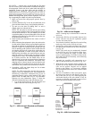
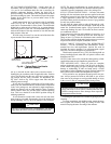
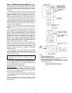
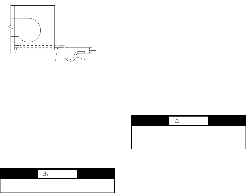
Install trapped drain line in accordance with all applicable
codes (see Fig. 48). A drain trap may be required by local
codes and is recommended for odor control. The differential
height inlet to outlet must be at least 1-in. wg greater than the
total static pressure of the unit. The differential height of the
outlet to the bottom of the trap must not be less than the total
static pressure of the unit.
Provide a trap of at least 2-in. near the end of the drain line
to prevent odors from entering the rooms.
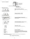
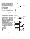
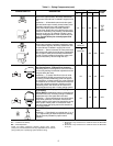
42C,D,V WATER SUPPLY/RETURN CONNECTIONS —
Install piping in accordance with all applicable codes. Position
valves over the drain pan. Be sure valves are in proper operat-
ing position and are easily accessible for adjustment. See
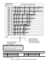
Fig. 44-47. Refer to Fig. 49 for copper water tube and joint
material pressure ratings.
If coil and valve package connections will be made with a
solder joint, care should be taken to ensure that the components
in the valve package are not subjected to high temperatures,
which may damage seals or other materials. Many 2-position
electric control valves are provided with a manual operating
lever. This lever should be in the OPEN position during all
soldering operations.
If coil connection is made with a union, the coil side of the
union must be prevented from turning (it must be backed up)
during tightening. See Fig. 44-47 for common valve packages.
NOTE: The project specifications for system pressure, pres-
sure drop limitations, and flow rate should be checked prior to
selection of specific components or the valve package size.
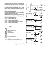
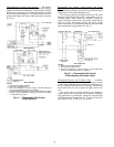
42C,D,V STEAM CONNECTIONS — On units with steam
heating coils, the maximum steam pressure applied to the unit
should never exceed 10 psig. However, when steam is used on
a 4-pipe application system with 1-row and 2-row coils the
maximum steam pressure should never exceed 5 psig (suitable
for only low pressure steam).
Do not drain the steam mains or take-off through the coils.
Drain the mains ahead of the coils through a steam trap to the
return line. Overhead returns require 1 psig of pressure at the
steam trap discharge for each 2 ft elevation to ensure continu-
ous condensate removal.
Proper steam trap selection and installation is necessary. As a
guideline in creating a steam trap locate the steam trap dis-
charge at least 12 in. below the condensate return connection.
This provides sufficient hydrostatic head pressure to overcome
trap losses and ensure complete condensate removal.
42C,D,V DIRECT EXPANSION (DX) REFRIGERANT
PIPING — Use the condensing unit manufacturer's recom-
mended line sizes and requirements. Suction line must be
insulated for correct operation. Use refrigerant-grade copper
lines only. The unit is not applied as a heat pump.
Thermostatic expansion valve (TXV) and sensing bulb are
factory-installed on units when DX coil option is chosen with
distributor and TXV.
NOTE: If a hot water coil is used in the reheat position, a field-
supplied freezestat must be installed to protect the coil.
TEST AND INSULATE — When all joints are complete,
perform hydrostatic test for leaks. Vent all coils at this time.
Check interior unit piping for signs of leakage from shipping
damage or mishandling. If leaks are found, notify a Carrier
representative before initiating any repairs. Release trapped air
from system (refer to Make Final Preparations section).
Never pressurize any equipment beyond specific test pres-
sure. Always pressure test with an inert fluid or gas, such as
clear water or dry nitrogen to avoid possible damage or injury
in the event of a leak or component failure during testing.
Following the hydrostatic test, insulate all piping to prevent
sweating.
To ensure compliance with building codes, restore the struc-
ture's original fire resistance rating by sealing all holes with
material carrying the same fire rating as the structure.
CAUTION
DO NOT OVERTIGHTEN! Overtightening will distort
(egg shape) the union seal surface and destroy the union.
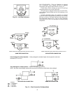
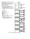
CONDENSATE
PAN STUB-OUT
7/8 IN. FIELD-SUPPLIED
DRAIN EXTENSION
TRAP
2 IN. MIN
Fig. 48 — Typical Drain Line Details
(42D Unit Shown)
CAUTION
All water coils must be protected from freezing after initial
filling with water. Even if system is drained, unit coils may
still have enough water to cause damage when exposed to
temperatures below freezing.