


45
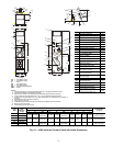
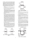
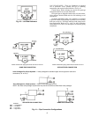
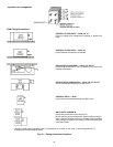
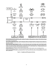
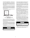
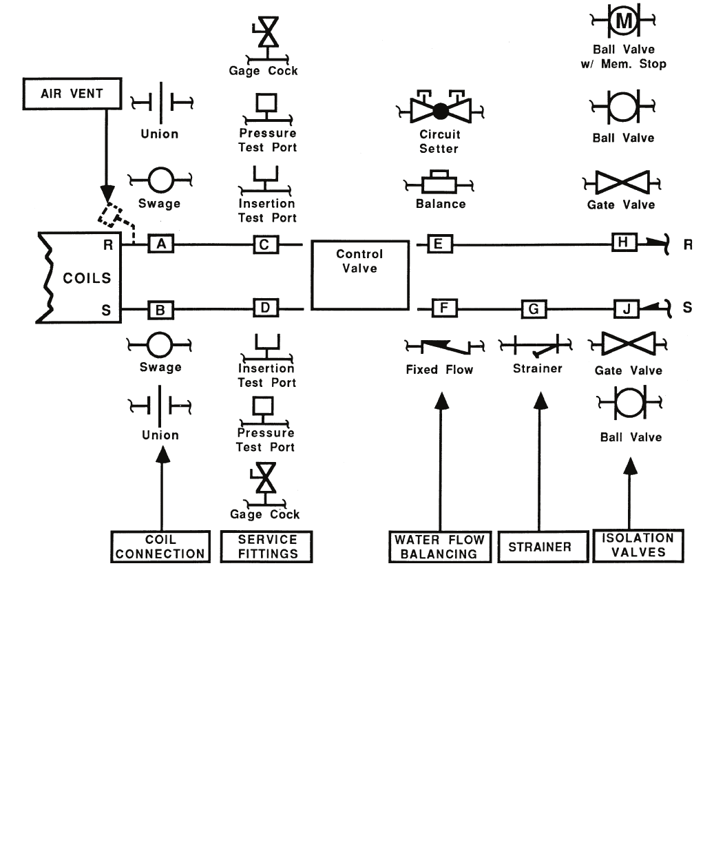
Fig. 43 — Symbols and Placement of Valves
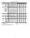
Coil Connections (Positions A & B) — When isolation valve only is added to supply or return line, the isolation valve will
be factory brazed to the coil stub-out. Addition of any other component or connection to the supply or return line will change
the respective coil connection(s).
Service Fittings (Positions C & D) — Optional fittings for attaching pressure/temperature sensing devices to obtain pres-
sure drop or temperature differential across coil. Used with ball valve or balance valve where extremely accurate water flow
balancing is required.
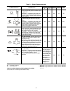
Water Flow Balancing (Positions E, F, & H) — Only one device per total valve package to be used for balancing water
flow through the coil. When isolation valve (ball valve or ball valve with memory stop at position H) is used for water flow bal-
ancing, do not specify additional balancing device at position E or F. When balancing device is specified at position E or F,
isolation valve does not require balancing feature at position H (with a 3-way motorized valve, a bypass balancing valve
may be specified in the bypass line to permit equal flow balancing).
Strainer (Position G) — Does not include blow down fitting and should not be used in lieu of main piping strainers.
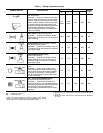
Isolation Valves (Positions H & J) — Normally requires one each on supply and return line (see exception under circuit
setter). When position H is used for balancing (ball valve or ball valve with memory stop), check specifications for service
valve requirements.