


43
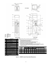
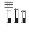
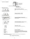
VALVE PACKAGES — There are limitations on physical
size of pneumatic valves, quantity and type of matching
components, and required control interface. See Fig. 43.
Consult factory before ordering any special valve package
components that are not covered in this book.
Valve packages are shipped with the units or in unit cartons.
Valve packages include belled ends for field soldering to coil
connections.
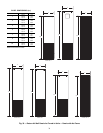
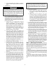
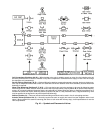
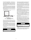
All factory-furnished cooling valve packages are arranged
to position as much of the package as possible over an auxiliary
drain pan or drip lip. This helps minimize field piping insula-
tion requirements. Refer to Fig. 44-47 for pipe connection
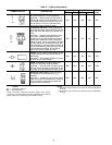
configurations. See Table 5 for descriptions of common piping
components.
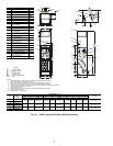
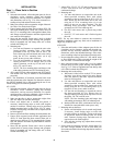
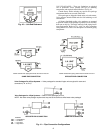
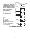
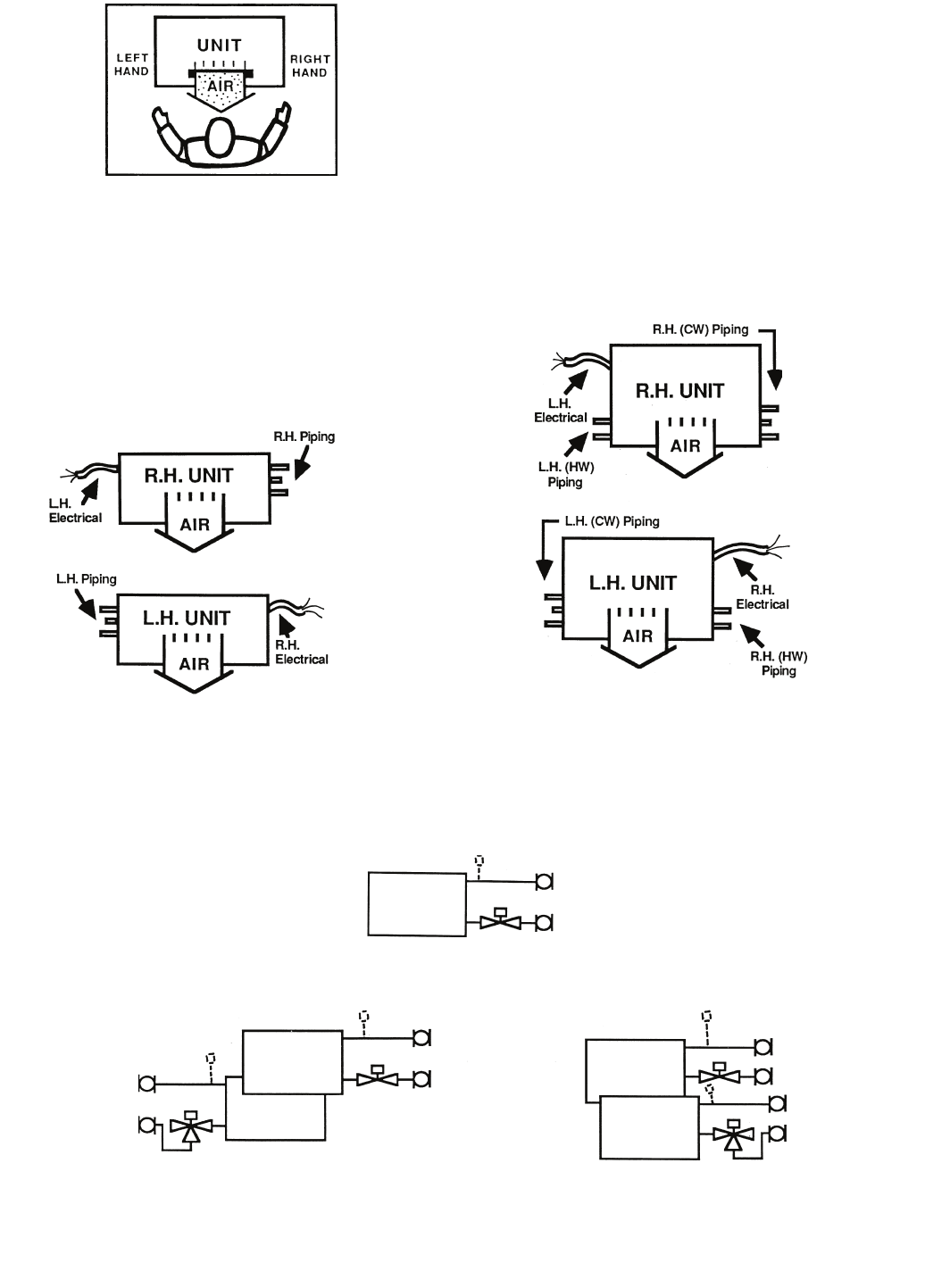
Fig. 40 — Unit End Reference
NOTE: Chilled water piping determines the hand of the unit.
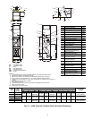
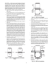
Fig. 41 — Pipe Connection Configurations
NOTE: Chilled water piping determines the hand of the unit.
SAME END CONNECTION
OPPOSITE END CONNECTION
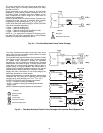
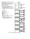
Valve Packages For 2-Pipe Systems — Valve packages for standard 2-pipe units are piped for same end
connection (L.H. or R.H.).
Valve Packages for 4-Pipe Systems — Select 2 valve packages per unit.
NOTE: Hot water valve package requirements may not be the same as chilled water valve package!
LEGEND
CW — Chilled Water
HW — Hot Water
LH — Left Hand
RH — Right Hand
SAME END CONNECTION
OPPOSITE END CONNECTION