


20
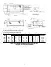
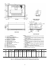
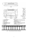
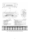
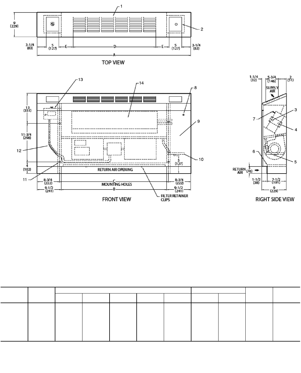
LEGEND
1— Standard Stamped Supply Grille
2— Access Door, Fan Switch
3— Supply Conn,
5
/
8
-in. OD
4— Return Conn,
5
/
8
-in. OD
5— Drain,
3
/
4
-in. MPT
6— Filter
7— Air Vent,
1
/
8
-in. MPT
8— Front Panel Fastener
9— Optional Valve Package (inside cabinet)
10 — Drain Pan, Auxiliary, Shipped Loose
11 — Wall Mounting Holes
3
/
4
-in. Diameter
12 — Flexible Conduit
13 — Fan Switch, 3 speed
14 — Access Doors
NOTES:
1. Right hand unit shown; left hand unit opposite. Coil connection
locations are ±
5
/
8
-in.
2. Unit sizes 02 and 03 have one motor, one blower; sizes 04
through 08 have one motor, 2 blowers; sizes 10 and 12 have
2 motors, 4 blowers.
3. Standard 3-row coil shown.
4. Cabinet has an Arctic White baked finish.
5. Not shown:
1
/
2
-in. fiberglass insulation on inside of casing,
closed cell foam on main drain pan.
6. For optional coil connections, view 42VA-203-1 using the Fan
Coil Builder.
7. Valve package is factory-installed inside the cabinet when
ordered with the unit (based on component size).
8. Dimensions shown in inches (mm).
*Unit weights are based on dry coils and minimum rows. Weights exclude packaging, valves, and other components.
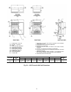
UNIT
SIZE
NOM
AIRFLOW
(Cfm)
DIMENSIONS (in.) QTY/UNIT FACE
AREA
(sq ft)
UNIT
WEIGHT*
(lb)
ABCDE
Blower Motor
02 200 41 22 23
1
/
2
17
1
/
4
3
5
/
8
1 1 0.83 92
03 300 45 26 27
1
/
2
21
1
/
2
3
1
/
2
1 1 1.08 98
04 400 51 32 33
1
/
2
26 4
1
/
4
2 1 1.35 122
06 600 61 42 43
1
/
2
39 2
3
/
4
2 1 1.88 141
08 800 63 44 45
1
/
2
39 3
3
/
4
2 1 2.31 144
10 1000 77 58 59
1
/
2
52
1
/
8
4
1
/
4
4 2 3.16 178
12 1200 85 66 67
1
/
2
61 3
3
/
4
4 2 3.65 205
A42-4111
Fig. 17 — 42VF Vertical Cabinet Unit with Slant Top Dimensions