


16
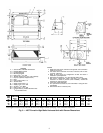
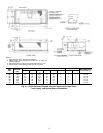
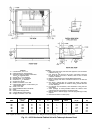
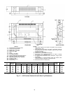
LEGEND
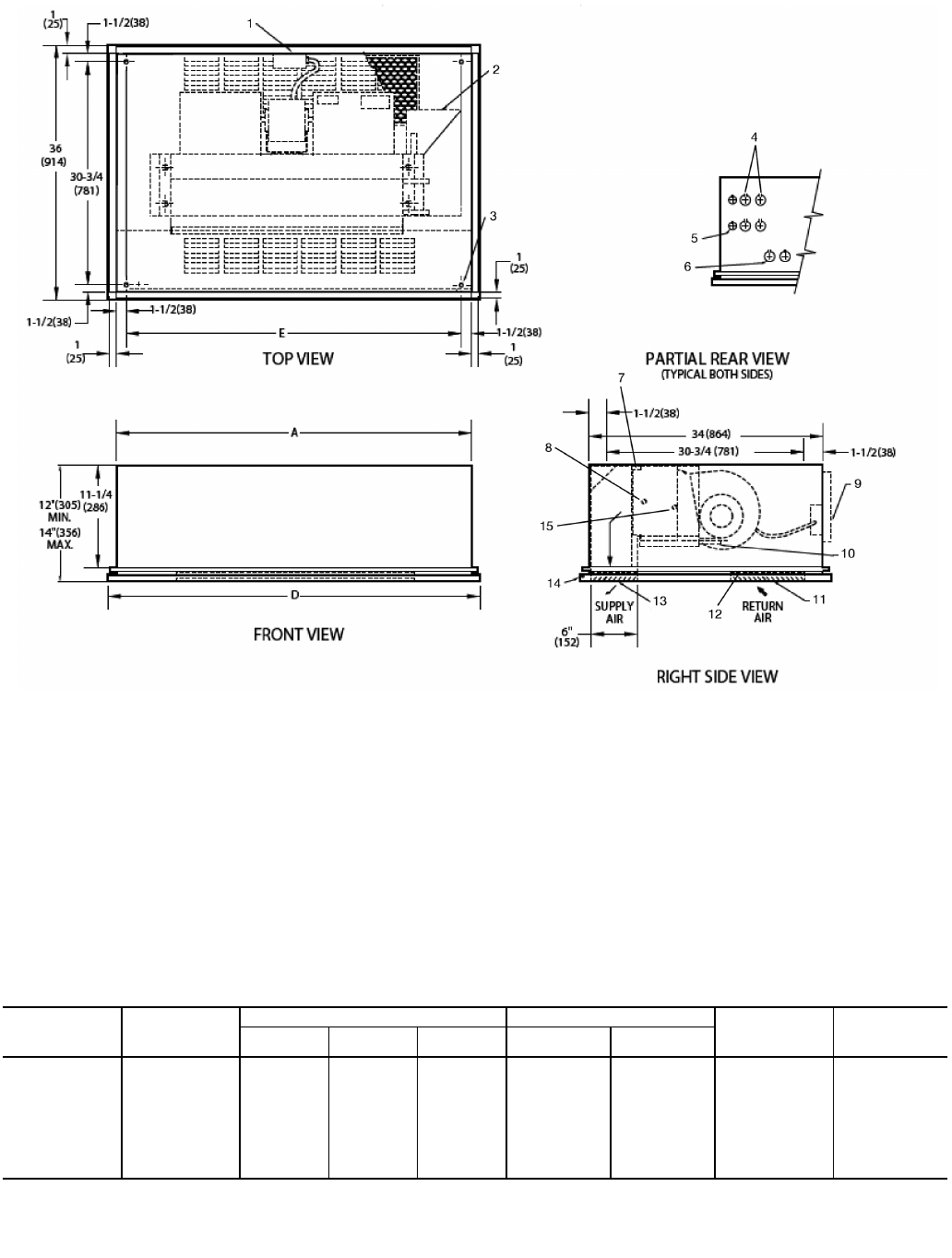
1— Junction Box, 4 in. x 4 in.
2— Optional Drip Lip, shipped loose
3— Mounting Holes (4), Rubber Grommets
have
3
/
8
-in. Diameter Hole
4— Piping KO, 1
1
/
2
-in. Diameter
5— Electrical KO,
7
/
8
-in. Diameter
6— Drain KO, 1
1
/
2
-in. Diameter
7— Supply Duct Collar
8— Return Connection,
5
/
8
-in. OD.
9— Optional Rear Return. Consult factory for
collar dimensions.
10 — Drain,
7
/
8
-in. OD.
11 — Stamped Bottom Return Air Grille
12 — Filter
13 — Stamped Air Supply Grille
14 — Hinged Bottom Access Panel
15 — Supply Connection,
5
/
8
-in. OD.
*Unit weights are based on dry coils and minimum rows. Weights exclude packaging, valves, and other components.
UNIT
SIZE
NOM
AIRFLOW
(Cfm)
DIMENSIONS (in.) QTY/UNIT
FACE AREA
(sq ft)
UNIT WEIGHT*
(lb)
ADE
Blower Motor
02 200 35 37 32 1 1 0.83 115
03 300 35 37 32 1 1 1.08 120
04 400 41 43 38 2 1 1.35 135
06 600 53 55 50 2 1 1.88 150
08 800 53 55 50 2 1 2.31 155
10 1000 75 77 72 4 2 3.16 227
12 1200 75 77 72 4 2 3.65 241
NOTES:
1. Right hand unit shown; left hand unit opposite. Coil connection
locations are ±
5
/
8
-in.
2. Unit sizes 02 and 03 have one motor, one blower; sizes 04
through 08 have one motor, 2 blowers; sizes 10 and 12 have
2 motors, 4 blowers.
3. Bottom access panel has an Arctic White baked finish.
4. Refer to supply and return connections above for coil stub-out
locations.
5. Not shown: optional drip lip, 3-speed fan switch; wall plate,
1
/
2
-in. fiberglass insulation on inside of casing, closed cell foam
on main drain pan.
6. For optional coil connections, view 42CA-203-1 using the Fan
Coil Builder.
7. Valve package is factory-installed inside the cabinet when
ordered with the unit (based on component size).
8. Bottom return or bottom supply is an ETO (engineering to order)
request.
9. Dimensions shown in inches (mm).
A42-4107
Fig. 13 — 42CK Horizontal Cabinet Unit with Telescopic Access Panel