


29
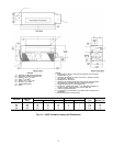
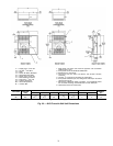
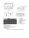
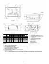
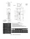
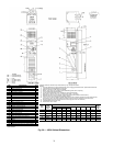
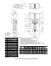
*Unit weights are based on dry coils and minimum rows. Weights exclude packaging, valves,
and other components.
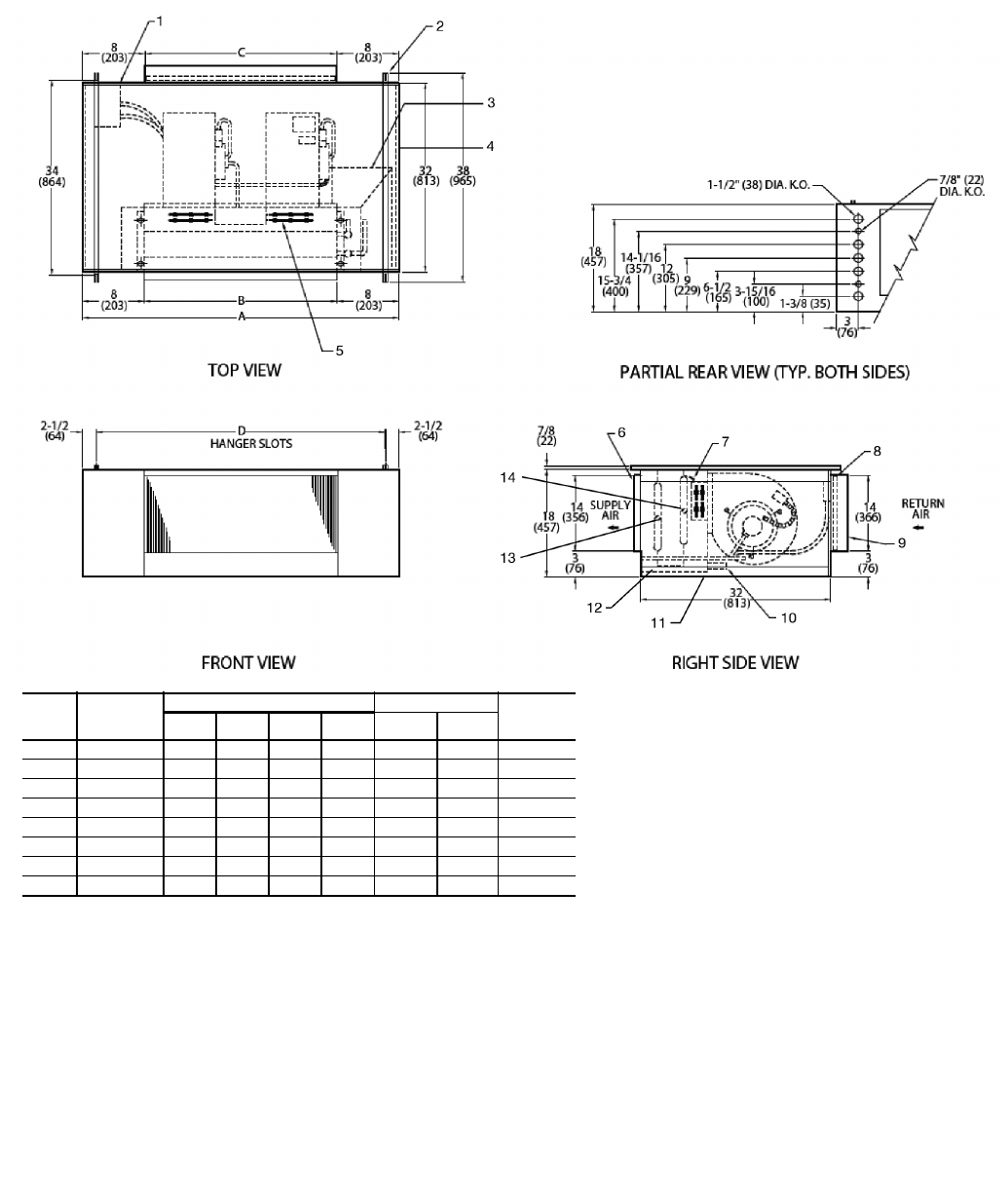
NOTES:
1. Right hand unit shown; left hand unit opposite.
2. Coil stub-out location data available on request.
3. Unit fabricated of galvanized steel.
4. Internal parts fabricated of galvanized steel.
5. Sizes 06, 08 and 10 have one motor, one blower. Sizes 12 through 20 have 2 motors,
2 blowers.
6. Units must have drain line pitched and trapped externally.
7. For optional coil connections, view 42DA-203-1 using the Fan Coil Builder.
8. Fan switch, wall plate not shown.
9. Galvanized finished provided as standard.
10. Dimensions are in inches (mm).
UNIT
SIZE
NOM
AIRFLOW
(cfm)
DIMENSIONS (in. ±
1
/
8
) QTY/UNIT UNIT
WEIGHT*
(lb)
ABCD
Blower Motor
06 600 31 15 15 26 1 1 150
08 800 36 20 20 31 1 1 160
10 1000 40 24 24 35 1 1 170
12 1200 45 29 29 40 2 2 195
14 1400 50 34 34 45 2 2 205
16 1600 55 39 39 50 2 2 215
18 1800 60 44 44 55 2 2 230
20 2000 64 48 48 59 2 2 235
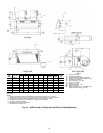
LEGEND
1— Motor Junction Box
2— Unit Mounting Channel (2), 14-gage; 4 Mounting
Slots,
1
/
2
-in. x 2-in.
3— Auxiliary Drip Lip (optional, shipped loose)
4— Side Access Panels
5— Electrical Strip Heater Element (optional)
6— Supply Air Duct Connection, 1 in.
7— Manual Air Vent
8— Filter, Throwaway, 1-in.
9— Return Air Duct Connection, 2
1
/
2
in.
10 — Drain,
7
/
8
-in. OD
11 — Bottom Access Panel
12 — Drain Pan
13 — Coil Inlet, Copper Sweat Connection
14 — Coil Outlet, Copper Sweat Connection
A42-4123
Fig. 26 — 42DE Ceiling Unit with Full Casing and Electric Heat Dimensions