


51
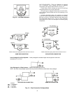
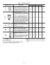
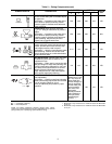
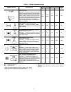
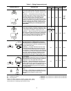
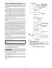
Table 5 — Piping Components (cont)
LEGEND
*Check all system component pressure ratings (coils, values,
pumps, etc.) with manufacturer and any applicable local or national
piping codes prior to specifying system pressure rating.
NOTES:
1. Motorized 2-way valves have a maximum close-off differential
of 25 psi.
2. Motorized 3-way valves have a maximum close-off differential
of 10 psi.
SYMBOL/SKETCH DESCRIPTION
C
V
FACTOR RATING*
STEAM
USE
1
/
2
in.
3
/
4
in. PSI F
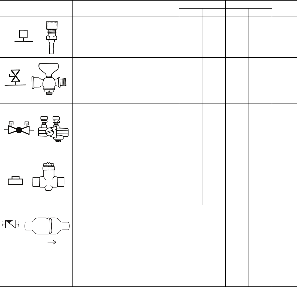
PRESSURE TEST PORT: Brass body
1
/
4
in.
service access fitting with removable depres-
sor type core.
Application — Installed on both sides of the
coil to allow for pressure sensing. Attach
pressure gages to facilitate close tolerance
water balancing.
N/A N/A 400 210 NO
GAGE COCK: Brass shut-off valve with
1
/
4
in. FPT fitting for attachment of pressure
gages.
Application — Installed on both sides of the
coil to allow for pressure sensing. Attach
pressure gages to facilitate close tolerance
water balancing. May be used in bleed
bypass line to regulate water flow.
N/A N/A 200 250 N/A
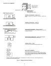
CIRCUIT SETTER: Variable water flow bal-
ancing valve with manual adjustment knob,
pointer, percent-open scale, memory stop
and integral pressure read-out ports.
Application — Used for close tolerance water
flow balancing. Positive shut-off ball valve
feature allows usage as combination balanc-
ing and shut-off valve.
2.12 3.9 300 250 NO
BALANCE VALVE: Variable water flow man-
ual balancing valve with screwdriver slot
adjustment screw.
Application — Often used in conjunction with
test port fittings for water flow balancing. Bal-
ance by temperature differential or coil pres-
sure drop (check specifications for service
fittings required if balancing by pressure
drop). May be used in 3-way valve bypass
line to permit equal flow balancing.
3.0 8.9 150 200 NO
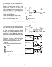
FIXED FLOW VALVE: Flexible orifice type
(non-adjustable).
Application — Used for water flow balancing.
Valve automatically adjusts the flow to within
10% of set point. Requires 15 psi
(35 ft) of additional pump head for proper
operation.
Valve orifice size
determines C
V
fac-
tor. The orifice of
these fixed flow
valves changes as
flow is regulated.
As the water pres-
sure increases,
the orifice size
decreases,
thereby automati-
cally limiting the
flow rate to the
specified gpm
(±10%).
150 160 NO
FLOW
Cv — Coefficient of Velocity
DX — Direct Expansion