


41
42S UNITS — A factory tag is on top of each unit. Tag states
riser tier number, floor, room number if furnished and supply-
air arrangement. Check unit for any other labels that apply to
installation. Remove unit from pallet and take directly to
assigned space for installation. Great care must be taken to
assure that no force or pressure be applied to the coil, risers or
piping during handling. Never use the riser to lift the unit. To
maintain the straight and square cabinet alignment, avoid lift-
ing or supporting the cabinet only at the top and bottom.
1. Begin on lowest floor and progress upward, floor by
floor, to top.
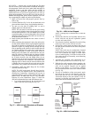
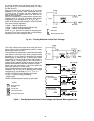
2. Examine drain line (Fig. 28-34). Be sure both ends are in
place and that it forms a trap. Avoid pinching drain line.
3. Tip unit over riser hole in building floor. As unit is
righted, align riser with unit below.
NOTE: The unit must be lowered into the space taking
care to properly align the risers to engage the riser swaged
section on the unit below. The riser should never be bent
or pushed together to be passed through the floor slot and
should never be lifted up or pulled down to meet the riser
on the floor below or above.
4. Install isolator pads beneath the four corners of unit if
applicable.
5. Before anchoring the equipment in place, the unit must be
leveled and the cabinet must be squared and brought into
line with any adjacent or included walls. The unit may be
anchored in place by bolting directly through the unit
floor or attaching to the cabinet in some location that will
not interfere with drywall or other items such as the sup-
ply grille, thermostat, or return access panel. When at-
taching to the unit cabinet, care must be taken to not pen-
etrate the cabinet in locations that may damage internal
components or wiring. The mounting technique is a mat-
ter of choice; however, the unit should always be an-
chored securely to prevent movement during construction
and riser expansion and contraction. On certain units,
shipping screws or braces must be removed after the unit
is installed. Be sure to check all tags on the unit to deter-
mine which, if any, of these devices need to be removed.
6. If installing a 42SJ unit, follow Steps a-h. For all other
42S units, continue to Step 7.
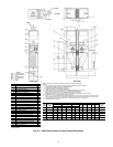
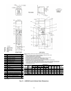
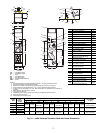
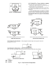
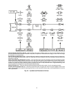
NOTE: The 42SJ back-to-back fan coils have been de-
signed to serve two separate rooms. These products are
classified by Underwriters Laboratories Inc. for use in
penetration firestop systems, control number 27WL when
ordered with 1-hr rated chase. See UL Fire Resistance
Directory for more information. Figure 37 shows the
42SJ unit with standard risers and with Siamese risers.
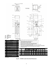
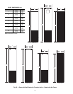
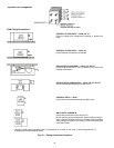
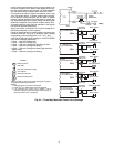
a. Lay out the control lines for the drywall track and
studs in the floor and ceiling (see Fig. 38).
NOTE: Tracking may be installed now or after the
unit is set.
b. Position the 42SJ fan coil assembly between two
rooms with the unit drywall separation spotted
over the wall control lines.
c. If not already installed, install the floor and ceiling
tracks up to and over the 42SJ fan coil unit.
d. Position the vertical studs and fasten into each of
the stud pockets formed into the chase side panels
(see Fig. 38).
NOTE: The studs may be mechanically fastened
to the 42SJ fan coil. Care should be taken, how-
ever, not to penetrate the supply or return water
risers or internal piping. Given the levelness of the
floor and/or the fan coil assembly, some shimming
may be necessary.
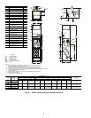
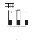
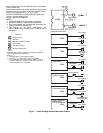
e. Assemble the specified wall construction up to
and over the top of the fan coil unit (see Fig. 39).
f. With the fire-wall separation being complete, the
drywall skin on the surface of the individual fan
coils can be applied. Drywall can be applied
directly to the surface, or, if necessary, studding
may be installed on the corners for vertical control
(see Fig. 39).
g. For ease of installation of the access panel, apply
drywall on the return air side directly to the sur-
face of the unit (see Fig. 39). When applying the
wall board directly to the unit cabinet, it may be
necessary to shim the wall board in some areas to
achieve the desired finished wall surface.
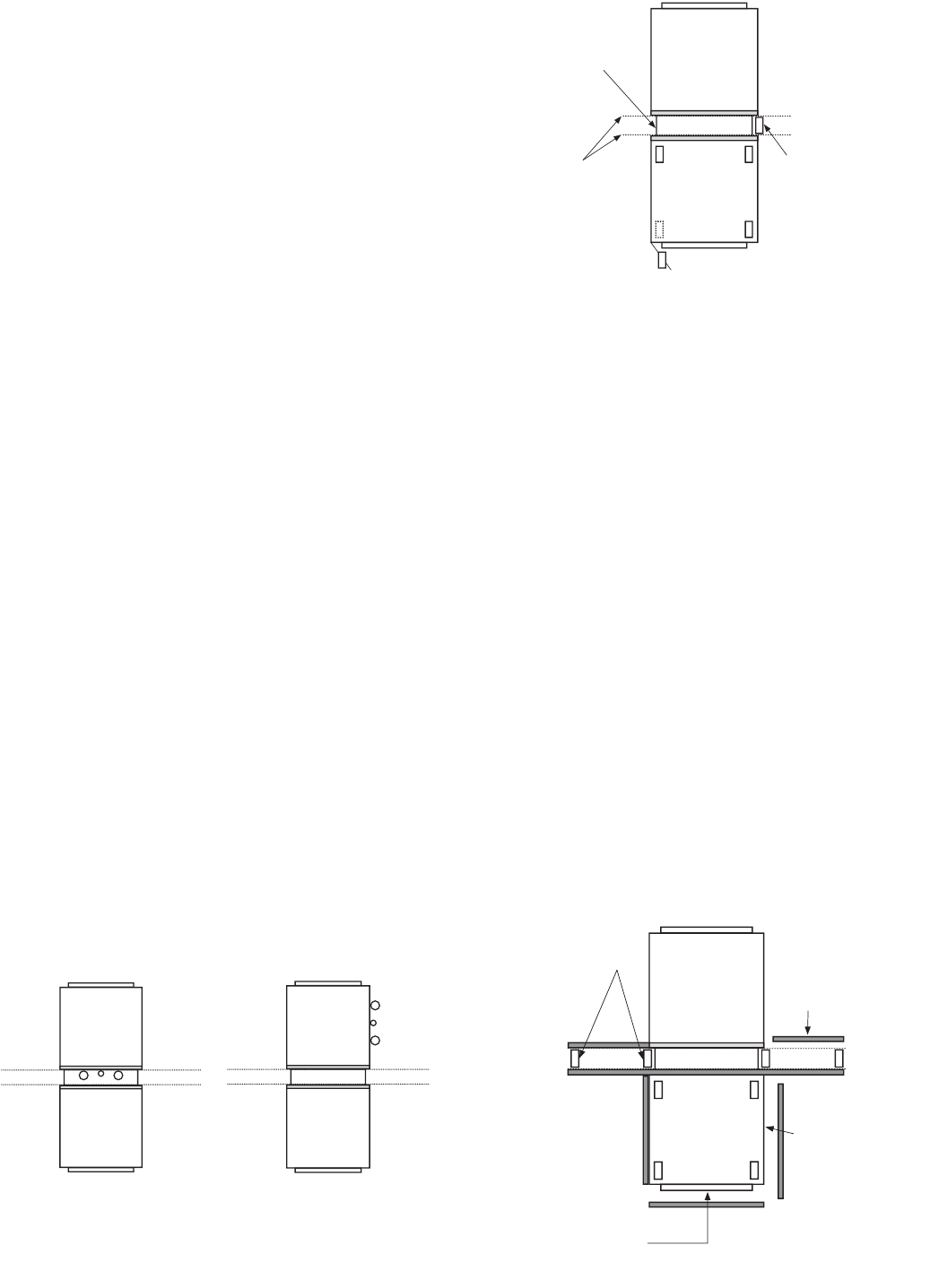
42SJB
42SJA
42SJB
42SJA
Fig. 37 — 42SJ Unit with Standard and Siamese
Risers
INSTALL WALL
STUD INTO
POCKET
FORMED BY
CHASE SIDE
PANEL
CHASE
SIDE
PANEL
DRYWALL
TRACK AND
STUD
CONTROL
LINES
INSTALL STUDS FROM TOP OF
UNIT TO CEILING (4 CORNERS)
Fig. 38 — 42SJ Unit as Shipped
WALL STUDS
INSTALL WALL
GYPSUM
BOARD
(TO WALL AND
OVER TOP OF
UNIT)
INSTALL
GYPSUM
BOARD TO
UNIT SIDES
INSTALL
GYPSUM
BOARD TO
FACE OF
UNIT WITH
CUT OUTS
FOR SUPPLY,
RETURN AND
THERMOSTAT
Fig. 39 — 42SJ Unit Installation