


28
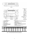
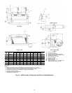
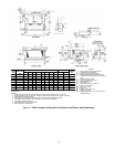
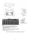
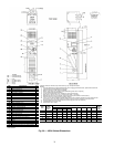
*Unit weights are based on dry coils and minimum rows. Weights exclude packaging, valves, and other
components.
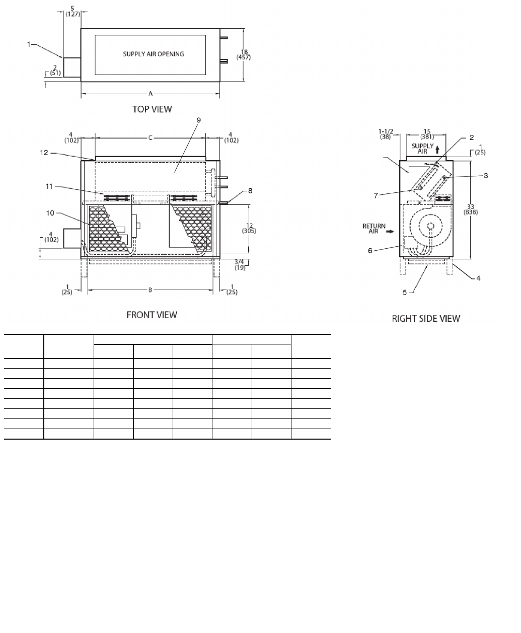
NOTES:
1. Right hand unit shown; left hand unit opposite. Coil connection locations are ±
5
/
8
inches.
2. Standard 4-row coil shown. Other coil option dimensional data available on request.
3. Sizes 06, 08 and 10 have one motor, one blower. Sizes 12 through 20 have 2 motors, 2 blowers.
4. Supply and return connections terminate within unit when valves are factory installed.
5. For optional coil connections, view 42DD-203-1 using the Fan Coil Builder.
6. Fan switch and wall plate are not shown.
7. Galvanized finish provided as standard.
8. Units with internal factory valve packages have external connections located in triangular section
above coil.
9. Consult Carrier for ducted front return air and external filter rack with 1-in. duct collar and throwaway
filters.
10. Units with electric heat require additional access on the side of unit for servicing contactor box.
11. With bottom return, access to filter is through the front access panel.
12. Dimensions are in inches (mm).
UNIT
SIZE
NOM
AIRFLOW
(cfm)
DIMENSIONS (in. ±
1
/
8
) QTY/UNIT UNIT
WEIGHT*
(lb)
ABC
Blower Motor
06 600 232115 1 1135
08 800 282620 1 1145
10 1000 32 30 24 1 1 155
12 1200 37 35 29 2 2 180
14 1400 42 40 34 2 2 190
16 1600 47 45 39 2 2 200
18 1800 52 50 44 2 2 215
20 2000 56 54 48 2 2 230
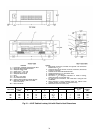
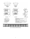
LEGEND
1— Motor Junction Box
2— Air Vent,
1
/
8
-in. MPT
3— Return Connection
4— Optional 6-in. Legs
5— Bottom Return (optional)
6— Return Air Opening
7— Supply Connection
8— Drain Connection,
7
/
8
-in. OD
9— Front Access Panel
10 — Filter, Throwaway
11 — Electric Strip Heater Element (optional)
12 — Supply Duct Connection, 1-in.
A42-4122
Fig. 25 — 42DD Vertical Unit with Full Casing and Electric Heat Dimensions
SEE NOTE 8