


48
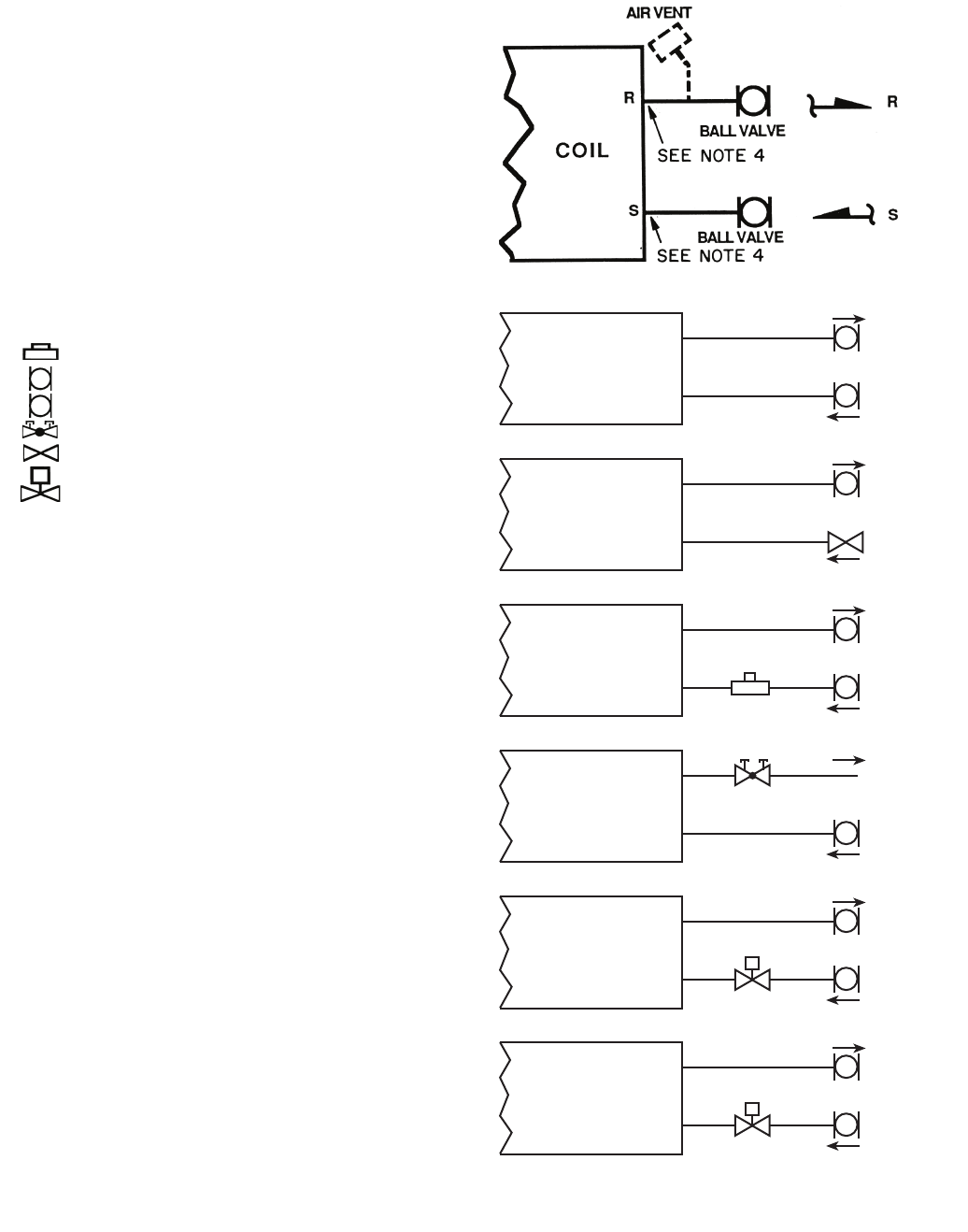
WITH HAND VALVES ONLY
BALL VALVE
BALL VALVE
(2) BALL
R
S
COIL
BALL VALVE
GATE SHUT
OFF VALVE
(1) BALL
(1) GATE
R
S
COIL
BALL VALVE
BALL VALVE
(2) BALL
(1) BALANCING
R
S
COIL
BALL VALVE
(1) BALL
(1) CIRCUIT SETTER
R
S
COIL
BALL VALVE
BALL VALVE
(2) BALL
(1) 2-WAY MOTORIZED
R
S
COIL
BALL VALVE (WITH
MEMORY STOP)
BALL VALVE
(2) BALL (ONE WITH
MEMORY STOP)
(1) 2-WAY MOTORIZED
R
S
COIL
BALANCING
VALVE
MOTORIZED
2-WAY VALVE
M
MOTORIZED
2-WAY VALVE
CIRCUIT SETTER
M
M
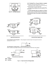
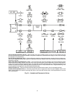
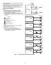
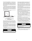
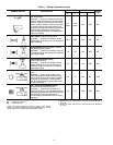
Fig. 47 — Valve Package without Motorized Control
When isolation valves only are specified, they will be brazed
to the coil stub-outs.
Check job specifications for system pressure, pressure drop
limitations and flow rate prior to selecting specific compo-
nents or valve package size (
1
/
2
in.,
3
/
4
in., etc.).
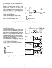
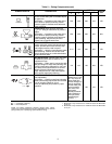
2-PIPE SYSTEM ONLY (One Valve Package) Application:
• 2 Pipe - Hydronic Heating Only
• 2 Pipe - Hydronic Cooling Only
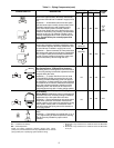
NOTES:
1. Continuous water flow, chilled water or hot water.
2. Not recommended for high humidity applications.
3. Not recommended with unit-mounted thermostat on
vertical units (except package R).
4. The addition of any other component(s) will
require swage fitting for field braze or optional union
connection.
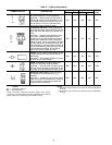
LEGEND
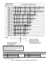
*When aquastat is used for automatic changeover, bypass is
required as indicated by dashed line.
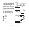
NOTES:
1. Packages factory furnished and installed.
2. Valves are
5
/
8
-in. ODS unless otherwise specified.
3. If an automatic flow control valve is added, it will be
located on supply line between shutoff valve and coil (or
motorized control valve, if supplied).
Balancing Valve
Ball Valve
Ball Valve with Memory Stop
Circuit Setter
Gate Shut Off Valve
Motorized 2-Way Valve
M