


47
CIRCUIT SETTER
(1) BALL
(1) CIRCUIT SETTER
(1) 3-WAY MOTORIZED
COIL
BALL VALVE
GATE
SHUT OFF VALVE
(1) GATE
(1) BALL
(1) 3-WAY MOTORIZED
R
S
COIL
BALL VALVE
BALL VALVE
(2) BALL
(1) BALANCING
(1) 3-WAY MOTORIZED
R
S
COIL
MOTORIZED
3-WAY VALVE
BYPASS
BALANCING
VALVE
MOTORIZED
3-WAY VALVE
BYPASS
(1) BALL
(1) 3-WAY MOTORIZED
R
S
COIL
BALANCING
VALVE
BALL VALVE
BALL VALVE
(WITH MEMORY STOP)
MOTORIZED
3-WAY VALVE
BYPASS
(2) BALL (ONE WITH
MEMORY STOP)
(1) 3-WAY MOTORIZED
R
S
COIL
BALL VALVE
BALL VALVE
MOTORIZED
3-WAY VALVE
BYPASS
R
S
COIL
BALL VALVE
MOTORIZED
3-WAY VALVE
BYPASS
M
M
M
M
M
M
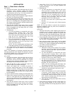
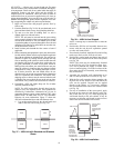
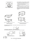
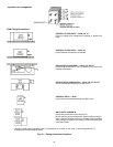
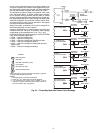
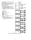
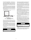
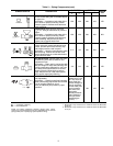
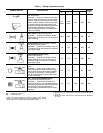
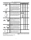
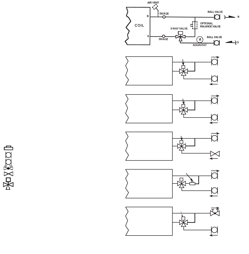
Fig. 46 — Three-Way Motorized Control Valve Package
On the 3-way motorized valve flow is normally closed to coil
and open to system return. Motor closes bypass flow to sys-
tem return while opening flow through coil. Water bypasses
coil and flows directly to system return when unit is OFF.
The aquastat (A) clips on supply line upstream from 3-way
valve (as shown above). It senses system water tempera-
ture to prevent cooling operation with hot water in system
piping or heating operation with chilled water in system pip-
ing. Aquastat(s) required for 2-pipe cooling and heating with
automatic changeover control and/or auxiliary electric heat.
A bypass balancing valve may be specified in the bypass
line to permit equal flow balancing.
Supply and return connections at coil will be swage fit for
field braze (standard) or unions (option).
Check job specifications for system pressure, pressure drop
limitations and flow rate prior to selecting valve package
components or valve package size (
1
/
2
in.,
3
/
4
in., etc.).
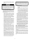
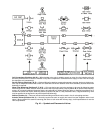
2-PIPE SYSTEM (One Valve Package) or 4-PIPE SYSTEM
(Two Valve Packages) Application:
• 2 Pipe — Hydronic Heating Only
• 2 Pipe — Hydronic Cooling Only
• 2 Pipe — Hydronic Cooling with Total Electric Heat
• 2 Pipe — Hydronic Cooling and Heating
• 2 Pipe — Hydronic Cooling and Heating with Auxiliary
Electric Heat
• 4 Pipe — Hydronic Cooling and Heating
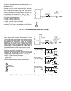
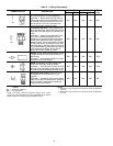
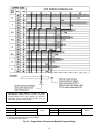
LEGEND
*When aquastat is used for automatic changeover, bypass is
required as indicated by dashed line.
NOTES:
1. Packages factory furnished and installed.
2. Valves are
5
/
8
-in. ODS unless otherwise specified.
3. If an automatic flow control valve is added, it will be
located on supply line between shutoff valve and coil (or
motorized control valve, if supplied).
Balancing Valve
Ball Valve
Ball Valve with Memory Stop
Circuit Setter
Gate Shut Off Valve
Motorized 3-Way Valve
M
MOTORIZED
MOTORIZED
M
a42-4176