


42
h. After all drywalling and painting is complete,
install thermostats, supply air grilles and return air
panels.
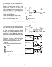
7. Attach unit risers:
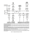
NOTE: The supply and return connections are marked on
the coil stub-outs and the valve package with an “S”
meaning supply or inlet and “R” meaning return or outlet
indicating flow direction to and from the coil. Blue letters
mark the chilled water connections and red letters mark
the hot water connections.
a. Each riser has a 3-in. swaged portion at top and
sufficient extension at bottom for an inserted
length of approximately 2-in. This unit-to-unit
joint is NOT intended for full bottoming in the
joint, but allows for variations in floor-to-floor
dimensions and for correct riser positioning.
If job requires that unit risers be supplemented
with between-the-floor extensions pieces may be
field-supplied or factory-supplied. If factory-
supplied, insulation is also provided.
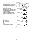
b. Level unit to ensure proper coil operation and
condensate drainage. Proper riser installation and
vertical positioning in the unit provides for a unit
piping run-out to the service valves which are cen-
tered in the access slots and level or sloping down
slightly away from the riser. This prevents con-
densation from running back to the riser and pos-
sible damage from dripping at the bottom of a
riser column. After units are positioned and riser
centered in pipe chase, make unit plumb in two
directions, using unit frame as a reference.
c. Anchor unit to building. Use bolts or lag screws
through holes provided in unit frame.
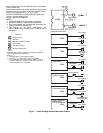
d. After all units in a stack are anchored, make unit-
to-unit riser joints. First, center each coil-to-riser
line within the expansion slot in the unit back
panel. Each riser joint must be in vertical
alignment with at least 1-in. penetration into the
swaged joint. This condition is met if floor-to-
floor dimension is as specified and coil-to-riser
lines are properly centered. Wide variations in
floor-to-floor dimensions may necessitate cutting
off or extending individual risers. Such modifica-
tions are the full responsibility of the installing
contractor.
e. Before making the riser joints, the riser insulation
must be pulled back away from the joint and pro-
tected from heat during the soldering process. Sol-
der riser joints with phos-copper, silfos, or other
high temperature alloy. The riser joint filler mate-
rial must be selected to withstand the total operat-
ing pressure (both static and pumping head) to
which the system will be subjected. Soft solder
(50-50, 60-40, or 85-15) or other low temperature
lead alloy is not suitable for this application.
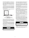
8. Anchor risers as required:
a. Do not fasten risers rigidly within each unit.
Risers must be free to move within pipe chase
in response to normal vertical expansion and
contraction.
b. Built in risers must be anchored at some point
to building structure. Unit design accommodates
up to 1
1
/
2
-in. expansion and contraction in riser
assemblies when positioned properly at the job
site. Risers must be anchored to the building struc-
ture to limit expansion and contraction movement
to a maximum of 1
1
/
2
-inches. Riser anchoring and
expansion compensation is not included in the fac-
tory-supplied unit and must be provided.
9. Test the system for leaks after the connections are com-
pleted. When testing with air or some other gas, it might
be necessary to tighten stem packing nuts on some valves
to maintain air pressure in the riser. Pressure testing risers
with water should be done with the unit service valves
closed to prevent flushing debris into the unit valve pack-
ages. This will also allow risers to be drained down after
testing in the winter to avoid freeze-up problems.
10. After system integrity has been established, pull the riser
insulation back into place over the joint and glue or seal
to prevent sweating and heat loss or gain. Internal chilled
water piping and valves are located over the drain pan
and need not be insulated.
11. If required, fireproof were necessary. Any fireproofing re-
quirements where risers or piping penetrate floors or
walls are the responsibility of the installer. This work
should be done only after all pressure testing is complet-
ed. The fireproofing method used must accommodate
pipe expansion and contraction and the piping must be
protected from abrasion and chemical attack. The pipe in-
sulation also must be maintained to prevent sweating and
must be protected from wear or erosion at the joint be-
tween the insulation and the fireproofing material.
Step 2 — Make Piping Connections — Access to
piping is available through the access panels at the side of the
units or front of the unit. Qualified personnel in accordance
with local and national codes must perform all piping connec-
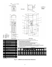
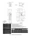
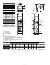
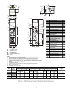
tions. Refer to Tables 1-4 for piping connections.
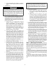
NOTE: It is important to have a common understanding of
which side of the unit is the right hand side and which is the
left hand side.
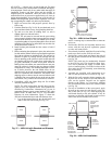
When facing the supply air outlet from the front of the unit
(air blowing in your face), your right hand will be on the right
side of the unit and your left hand will be on the left side of the
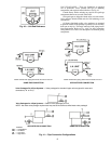
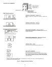
unit. See Fig. 40. Refer to Fig. 41 and 42 for typical piping
connections.
The supply and return piping connections of the factory-
provided valve package are either swaged for field brazing
(standard) or union fitted (optional) for field connection to the
coil.
CAUTION
Toxic residues and loose particles resulting from manufac-
turing and field piping techniques such as joint compounds,
soldering flux, and metal shavings may be present in the
unit and the piping system. Special consideration must be
given to system cleanliness when connecting to solar,
domestic or portable water systems. Failure to heed this
warning could result in equipment damage.
IMPORTANT: Chilled water and hot water risers should
never be piped to drain down into the condensate riser.
Extensive water damage can occur due to drain over-
flow. Drain chilled and hot water risers to a remote loca-
tion away from the unit such as sink, room and floor
drains.