


23
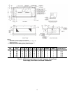
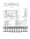
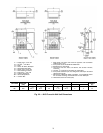
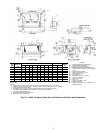
*Unit weights are based on dry coils and minimum rows. Weights exclude packaging, valves, and other components.
UNIT SIZE
NOM
AIRFLOW
(Cfm)
DIMENSIONS (in.) QTY/UNIT
FACE AREA
(sq ft)
UNIT
WEIGHT*
(lb)
ABDC
Blower Motor
02 200 41
22
3
3
/
4
17 2 1 1.18 72
03 300 46
27
421
1
/
2
2 1 1.53 100
04 400 54
35
3
5
/
8
30
1
/
4
2 1 2.08 108
06 600 68
49
4
1
/
16
43
3
/
8
4 2 3.06 154
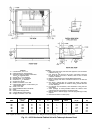
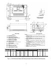
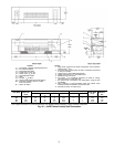
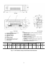
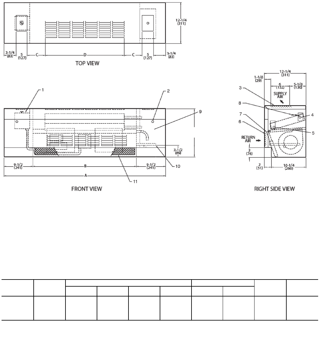
LEGEND
1— Fan Switch, 3-Speed, behind Access Door
2— Front Panel Fastener
3— Stamped Supply Grille
4— Supply Conn,
5
/
8
-in. OD
5— Return Conn,
5
/
8
-in. OD
6— Stamped Return Grille
7— Filter
8— Air Vent,
1
/
8
-in. MPT
9— Optional Valve Package (inside cabinet)
10 — Drain Pan, Auxiliary, with
3
/
4
-in. MPT
Drain Connection
11 — Return Air Grille
NOTES:
1. Right hand unit shown; left hand unit opposite. Coil connection
locations are ±
5
/
8
-in.
2. Unit sizes 02 through 04 have one motor, 2 blowers; size 06 has
2 motors, 4 blowers.
3. Cabinet has an Arctic White baked finish.
4. Height increases by 2 in. with electric heat.
5. Standard 2-row coil shown.
6. Not shown:
1
/
2
-in. fiberglass insulation on inside of casing,
closed cell foam on main drain pan.
7. For optional coil connections, view 42VC-203-1 using the Fan
Coil Builder.
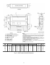
8. Valve package is factory-installed inside the cabinet when
ordered with the unit (based on component size).
9. Dimensions shown in inches (mm).
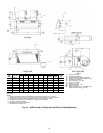
A42-4114
14-3/8
(368)
Fig. 20 — 42VE Cabinet Lowboy Unit Dimensions