


55
Step 3 — Make Electrical Connections — Refer
to unit nameplate for required supply voltage, fan and heater
amperage and required circuit ampacity. Refer to unit wire dia-
gram for unit and field wiring. Make sure all electrical connec-
tions are in accordance with unit wiring diagram and all appli-
cable codes.
The fan motor(s) should never be controlled by any wiring
or device other than the factory-supplied switch or thermostat/
switch combination unless prior factory authorization is
obtained. Fan motor(s) may be temporarily wired for use
during construction only with prior factory approval and only
in strict accordance with the instructions issued at that time.
Floor cabinet type units have factory-wired integral fan
switches. Connect power wires to leads in unit junction box per
unit wiring diagram. On the other units, install remote fan
switch according to job drawings. Hook up switch and power
wiring per unit wiring diagram.
Install optional, wall-mounted thermostat per instructions
shipped with thermostat. Connect as shown on unit wiring
diagram.
Units with factory-supplied and factory-installed aquastats
may be shipped with the aquastats mounted on a coil stub-out.
If this is the case, remove the aquastat before installing valve
package. When reinstalling aquastats, consult the factory-
piping diagram in the submittal for proper location. If the valve
package is field-supplied, the aquastat must be installed in a
location where it will sense the water temperature regardless of
the control valve position. A bleed bypass may be required to
guarantee proper aquastat operation. The aquastat bypass line
allows a small amount of water to flow from the supply to the
return piping when the control valve is closed.
NOTE: The aquastat must be able to sense whether the
flowing water is being chilled or heated and switches a contact
closed to provide automatic summer or winter changeover for
the system. When a two-pipe cooling/heating system with
optional auxiliary electric heat is desired, an additional
aquastat is required.
All field wiring must be in accordance with governing
codes and ordinances. Any modification of unit wiring without
factory authorization will invalidate all factory warranties and
nullify any agency listings.
Units may be equipped with line voltage controls or
24 VAC control systems. The following descriptions are for
line voltage controls only. For 24 v control operating sequence,
refer to thermostat operating instructions.
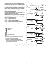
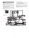
STANDARD WIRING PACKAGES
M
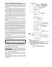
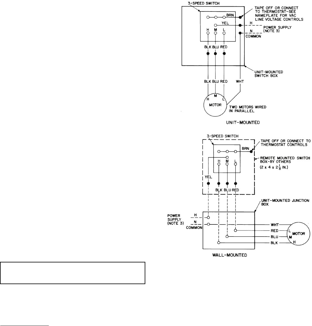
anual Fan Control — On all vertical cabinet units, the stan-
dard fan-speed switch is furnished unit-mounted and wired.
See Fig. 50. On all vertical furred-in units and all horizontal
units, the switch is shipped separately on a decorative wall
plate for field mounting and wiring.
The standard switch has LOW, MEDIUM, HIGH and OFF
positions plus an auxiliary contact to energize thermostats,
valves, dampers, etc.
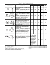
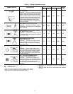
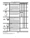
NOTE: Wiring diagrams are for 120-v power supply. If other
voltages for heaters or controls are specified, wiring may differ
from that shown.
IMPORTANT: Wiring diagrams shown depict typical
control functions. Refer to unit wiring label for specific
functions.
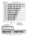
Fig. 50 — Manual Fan Control
NOTES:
1. Motors are thermally protected.
2. Use copper conductors only.
3. See unit nameplate for power supply. Provided disconnect
means and overload protection as required.
4. Unit-mounted thermostats are not recommended for fan control
because of poor temperature sensing. Fan control not available
on 42VC,VE lowboy units.