


19
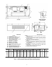
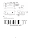
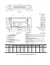
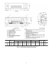
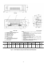
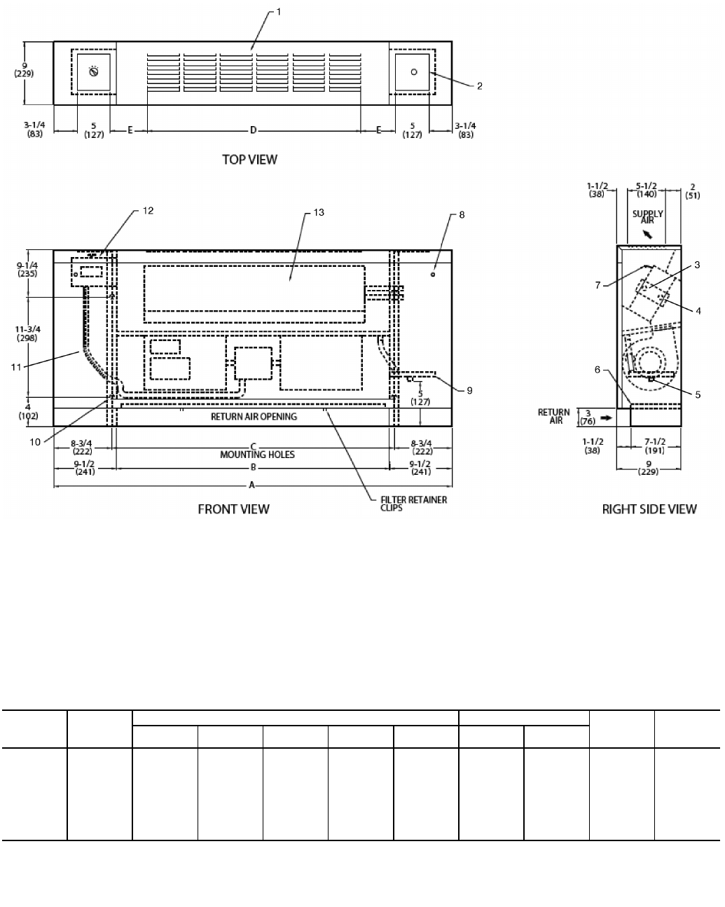
LEGEND
1— Standard Stamped Supply Grille
2— Access Door, Fan Switch
3— Supply Conn,
5
/
8
-in. OD
4— Return Conn,
5
/
8
-in. OD
5— Drain,
3
/
4
-in. MPT
6— Filter
7— Air Vent,
1
/
8
-in. MPT
8— Front Panel Fastener
9— Drain Pan, Auxiliary, Shipped Loose
10 — Wall Mounting Holes (4),
3
/
4
-in. Diameter
11 — Flexible Conduit
12 — Fan Switch, 3-speed
13 — Front Access Panel
NOTES:
1. Right hand unit shown; left hand unit opposite. Coil connection
locations are ±
5
/
8
-in.
2. Unit sizes 02 and 03 have one motor, one blower; sizes 04 through
08 have one motor, 2 blowers; sizes 10 and 12 have 2 motors,
4 blowers.
3. Standard 3-row coil shown.
4. Cabinet has an Arctic White baked finish.
5. Stamped supply grille standard. Optional single or double deflec-
tion grilles available.
6. Not shown:
1
/
2
-in. fiberglass insulation on inside of casing, closed
cell foam on main drain pan.
7. For optional coil connections, view 42VA-203-1 using the Fan Coil
Builder.
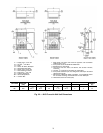
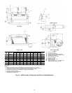
8. Dimensions shown in inches (mm).
*Unit weights are based on dry coils and minimum rows. Weights exclude packaging, valves, and other components.
UNIT
SIZE
NOM
AIRFLOW
(Cfm)
DIMENSIONS (in.) QTY/UNIT FACE
AREA
(sq ft)
UNIT
WEIGHT*
(lb)
ABCDE
Blower Motor
02 20041 2223
1
/
2
17
1
/
4
3
5
/
8
1 1 0.83 89
03 30045 2627
1
/
2
21
1
/
2
3
1
/
2
1 1 1.08 95
04 40051 3233
1
/
2
26 4
1
/
4
2 1 1.35 116
06 60061 4243
1
/
2
39 2
3
/
4
2 1 1.88 134
08 80063 4445
1
/
2
39 3
3
/
4
2 1 2.31 137
10 100077 5859
1
/
2
52 4
1
/
4
4 2 3.16 169
12 120085 6667
1
/
2
61 3
3
/
4
4 2 3.65 192
A42-4110
Fig. 16 — 42VB Vertical Cabinet Unit Dimensions