


18
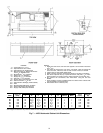
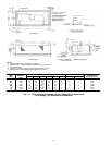
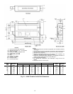
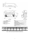
LEGEND
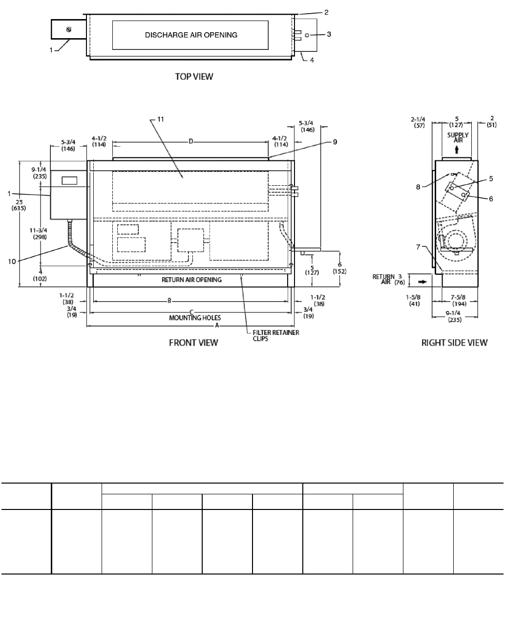
1— Optional Unit Mounted Control Box
2— Wall Mounting Holes (4),
3
/
4
-in. Diameter
3— Drain,
3
/
4
-in. MPT
4— Drain Pan, Auxiliary, Shipped Loose
5— Supply Conn,
5
/
8
-in. OD
6— Return Conn,
5
/
8
-in. OD
7— Filter
8— Air Vent,
1
/
8
-in. MPT
9— Discharge Opening
10 — Flexible Conduit
11 — Front Access Panel
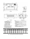
*Unit weights are based on dry coils and minimum rows. Weights exclude packaging, valves, and other components.
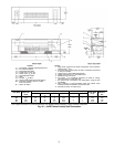
UNIT
SIZE
NOM
AIRFLOW
(Cfm)
DIMENSIONS (in.) QTY/UNIT FACE
AREA
(sq ft)
UNIT
WEIGHT*
(lb)
ABCD
Blower Motor
02 200 25 22 23
1
/
2
16 1 1 0.83 65
03 300 29 26 27
1
/
2
20 1 1 1.08 80
04 400 35 32 33
1
/
2
26 2 1 1.35 90
06 600 45 42 43
1
/
2
36 2 1 1.88 112
08 800 47 44 45
1
/
2
38 2 1 2.31 115
10 1000 61 58 59
1
/
2
52 4 2 3.16 140
12 1200 69 66 67
1
/
2
60 4 2 3.65 170
NOTES:
1. Right hand unit shown; left hand unit opposite. Coil connection locations
are ±
5
/
8
-in.
2. Unit sizes 02 and 03 have one motor, one blower; sizes 04 through 08
have one motor, 2 blowers; sizes 10 and 12 have 2 motors, 4 blowers.
3. Standard 3-row coil shown.
4. Optional unit-mounted switch box and controls, when specified, are
installed on opposite side from cooling connections.
5. Not shown: 3-speed fan switch; wall plate,
1
/
2
-in. fiberglass insulation on
inside of casing, closed cell foam on main drain pan.
6. Units have galvanized finish.
7. For optional coil connections, view 42VA-203-1 using the Fan Coil
Builder.
8. Dimensions shown in inches (mm).
A42-4109
Fig. 15 — 42VA Furred-In Vertical Unit Dimensions