


33
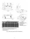
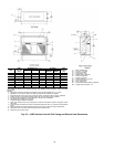
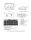
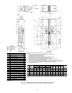
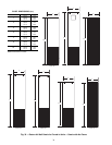
†Unit weights are based on dry coils and minimum rows. Weights exclude packaging, valves, and other components.
UNIT
SIZE
NOM
AIRFLOW
(cfm)
DIMENSIONS (in.)
UNIT
WEIGHT†
(lb)
Single Supply Double Supply Top Supply
EGHI J
ABABCD
03 300 14 8 14 6 14 10 17 1
1
/
2
1
1
/
2
14 40
1
/
4
360
04 400 14 12 14 6 14 10 17 1
1
/
2
1
1
/
2
14 40
1
/
4
450
06 600 18 10 18 6 16 12 20 1 2 18 46
1
/
4
480
08 800 18 12 18 6 16 12 20 1 2 18 46
1
/
4
520
10 1000 ——22 8181624132254
1
/
4
560
12 1200 ——22 8181624132254
1
/
4
610
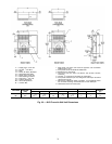
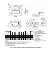
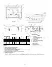
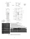
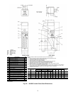
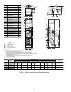
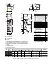
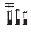
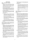
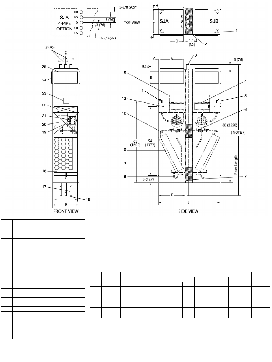
*Drawing provided for reference only. Dimensions may vary with options ordered.
NOTES:
1. Units are fabricated of 18-gage galvanized steel with a 16-gage galvanized fan deck.
2. All risers are insulated with
1
/
2
-in. closed cell insulation.
3. Thermostats shipped loose for field connection.
4. Risers are piped to coil with valves as specified.
5. Blower, motor, valves, coil, and filter are accessible through the return air opening.
6. Unit and control box are insulated with
1
/
2
-in. coated fiberglass insulation.
7. Riser length = [(floor to floor) +2 in.], maximum riser length = 115 inches.
8. Maximum riser size is 2
1
/
2
-in. diameter. If larger sizes are required, please consult the factory.
9. Expansion loops in hot water heating circuits as required.
10. A 9-in. x 2
1
/
4
-in. slot is provided in the inside back panel for coil connection penetration to permit expansion
and contraction of risers. Care must be taken to position the risers so that coil connection is at center of slot.
11. Drawing is pictorial (see unit arrangements for actual supply and return air orientation).
12. All dimensions are in inches.
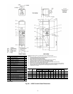
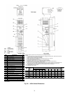
**Factory-Installed.
††Field-Installed.
ITEM DESCRIPTION QTY
1 Electrical Knockouts
2
2
Gypsum Board,
5
/
8
-in. Type “X” 1
3 3-in. Expanded Section 3/5
4 Strip Heater**(Optional) 2
5 Limit Switch**†† (Optional) 2
6
1
/
2
-in. Isolation Ball Valves** 4/8
7
Thermafiber Insulation 2
8 Flexible Drain Tube/P-Trap 2
9 Coil
1
/
2
-in. OD Copper Tube
2
10 Filter, Throwaway, 1-in.** 2
11 Return Air Opening 2
12 Air Vent, Manual 2
13 Knockout (For Optional Remote Mounting) 2
14 Molex Connector for Field Installed Stat 2
15 Control Box 2
16 Riser, Drain (Copper) 1
17 Riser, Supply and Return (Copper) 2/4
18 Drain Pan 2
19 Return Air Blockoff Panel (Optional)
1
20 Blower 2
21 Motor, 3-Speed, PSC, with Quick Connect 2
22 Access Panel (Control Box) 2
23 Control Opening (Surface Mount Stat) 2
24 Duct Collar,
1
/
2
-in. Extension (Typical)
1/2/3
25 Supply Air Opening(s) 1/2/3
LEGEND
CR— Cold Water Return
CS — Cold Water Supply
D—Drain
HR— Hot Water Return
HS — Hot Water Supply
R—Return
S—Supply
A42-4127
Fig. 30 — 42SJ Back-to-Back Furred-In Stack Dimensions