


37
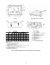
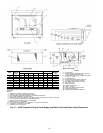
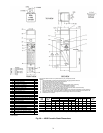
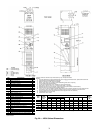
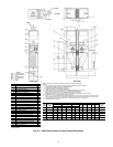
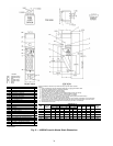
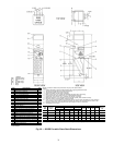
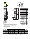
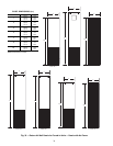
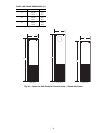
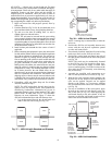
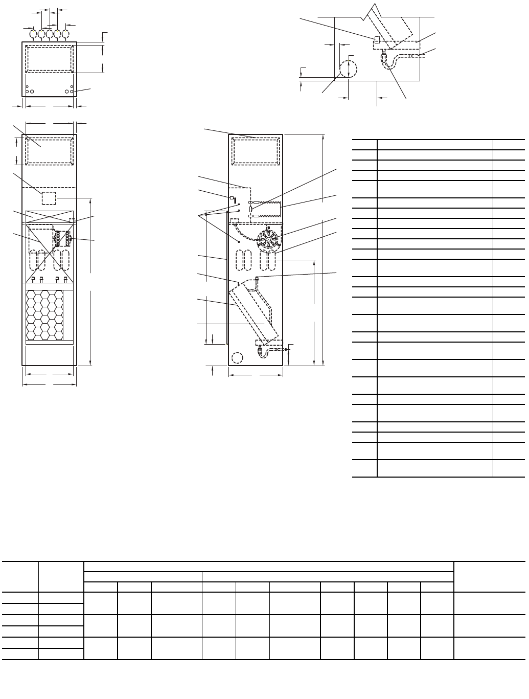
Fig. 34 — 42SU Universal Furred-In Stack with Heater Dimensions
*Unit weights are based on dry coils and minimum rows. Weights exclude packaging, valves, and other components.
UNIT
SIZE
UNIT
WEIGHT*
lb (kg)
DIMENSIONS, in. (mm)
FILTER SIZE
in. (mm)
Side Supply Top Supply
AB Size CD Size EFHI
03 360 (163)
14 (356) 12 (305)
14 x 12
(356 x 305)
14 (356) 10 (254)
14 x 10
(356 x 254)
17 (432) 3 (76) 1
1
/
2
(38) 14 (356)
12
1
/
2
x 24
1
/
4
x 1
(318 x 616 x 25)
04 450 (204)
06 480 (218)
18 (457) 12 (305)
18 x 12
(457 x 305)
16 (406) 12 (305)
16 x 12
(406 x 305)
20 (508) 1 (25) 2 (51) 18 (457)
16
1
/
4
x 26
3
/
4
x 1
(413 x 679 x 25)
08 520 (236)
10 560 (254)
22 (559) 16 (406)
22 x 16
(559 x 406)
18 (457) 16 (406)
18 x 16
(457 x 406)
24 (610) 1 (25) 3 (76) 22 (559)
20
1
/
2
x 29
1
/
4
x 1
(521 x 743 x 25)
12 610 (277)
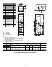
NOTES:
1. Units are fabricated of 18-gage galvanized steel with a 16-gage galvanized fan deck.
2. Thermostats shipped loose for field connection.
3. Blower, motor, valves, coil, and filter are accessible through the return air opening.
4. Unit and control box are insulated with
1
/
2
-in. (13 mm) coated fiberglass insulation.
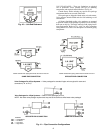
5. All risers will ship separately from units. Riser dimensions are measured from centerline of
knockout.
6. Drain knockouts on three sides of cabinet.
7. Flex hoses ship with unit.
8. Thread fittings on both ends of flex hoses must be field tightened and leak tested.
9. Return air panel not shown.
10. All dimensions are in inches (mm).
LEGEND
CR — Cold Water Return
CS — Cold Water Supply
D—Drain
HR — Hot Water Return
HS — Hot Water Supply
PSC — Permanent Split Capacitor
SWT — Sweat
6
5
8
(203)
51
(1295)
I
E
21
10
16
25
17
24
12
13
11
3
7
2
E
63
(1600)
23
14
15
19
9
8
18
A
B
F
C
L
39
(991)
5
(127)
1-1/4
(32)
4
(102)
5
(127)
88
(2235)
H
R
H
S
C
R
C
S
D
1-1/4
(32)
HCH
HR CR CSHS D
3-5/8
(92)
3-5/8
(92)
3
(76)
3
(76)
4
1-1/4
(32)
1
22
20
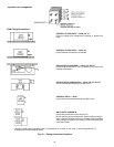
Item Description Qty
1 Float Switch (Optional) 1
2 Drain Pan 1
3 Flexible Drain Tube/P-Trap 1
4 Drain Knockout (3 Sides)
1 each
side
5 Limit Switch (Factory Installed) 1
6 Strip Heater 1
7 Blower 1
8 Riser Knockouts (3 Sides) 2/4
9 1/2 in. Flare Adaptor (SWT x 37.5) 2/4
10 Coil, 1/2 in. OD Copper Tube 1
11
1 in. Throwaway Filter
(Factory Installed)
1
12 Manual Air Vent 1
13 Return Air Opening 1
14
Knockout (For Optional
Thermostat Remote Mounting)
3
15
Molex Connector for
Field-Installed Thermostat
1
16 Control Box 1
17
Duct Collar Extension
(1/2 in. Side, 1 in. Top)
1/2/3
18
Outside Air Knockout
(On Each Side Panel)
1
19
Electrical Knockouts
(Near Each Side)
1
20 Service Switch (Optional) 1
21
Motor, 3-Speed, PSC,
with Quick Connect
1
22 Coil Blockoff Plate 1
23 Access Panel (Control Box) 1
24
Control Opening Knockout
(Surface Mount Thermostat)
1
25
Supply Air Openings
(4 Sides and Top, Stitch Cut)
1/2/3
a42-4155