


53
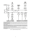
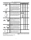
Table 5 — Piping Components (cont)
LEGEND
*Check all system component pressure ratings (coils, values,
pumps, etc.) with manufacturer and any applicable local or national
piping codes prior to specifying system pressure rating.
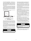
NOTES:
1. Motorized 2-way valves have a maximum close-off differential
of 25 psi.
2. Motorized 3-way valves have a maximum close-off differential
of 10 psi.
SYMBOL/SKETCH DESCRIPTION
C
V
FACTOR RATING*
STEAM
USE
1
/
2
in.
3
/
4
in. PSI F
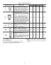
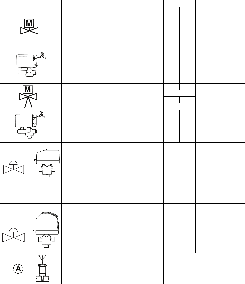
2-WAY MOTORIZED VALVE: Electric 2-position flow
control valve (open/closed). Normally closed body
with manual override lever. Installed in supply line to
unit.
Application — All standard control and valve pack-
ages are based upon normally closed valves (valve
electrically powered open and closed by spring
return when electric power removed). Manual
override lever allows valve to be placed in the open
position for secondary (unit) flushing, constant water
flow prior to start-up, etc. Manual override is auto-
matically disengaged when valve is electrically acti-
vated. Consult factory for normally open valve
applications.
2.3 2.3 300 200
YES
15
PSI
MAX.
3-WAY MOTORIZED VALVE: Electric 2-position flow
control valve (closed to coil/open to bypass or open
to coil/closed to bypass). Normally closed with man-
ual override lever. Installed in supply line to unit.
Application — Same comments as 2-way motorized
valve except with manual override lever engaged the
valve is open to both ports and water flow will take
the path of least resistance through the valve pack-
age (not necessarily 100% through the coil).
5.0 5.0
300 200 N/A
SERVICE
2.8 2.8
BYPASS
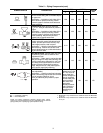
MODULATING VALVE (Optional)
(Non-Spring Return, Floating Point Actuator):
Modulating valves are designed to control the flow in
the circuit by making incremental adjustments to the
flow path within the valve.
Application — To control fluid flow in fan coil units.
On the 42DD,SG,SJ,SH commercial fan coil units,
the factory-provided modulating valve has applica-
tion restrictions. In these models, the valve packages
are located in the air stream, downstream of the coil.
Due to the ambient temperature limitations of the
modulating valves, the valves can be used in the
units listed above only with a 2-pipe cooling system.
4.0
300 200 N/A
MODULATING VALVE (Requires ETO [Engineer-
ing to Order])
(Spring Return): Modulating valves are designed to
control the flow in the circuit by making incremental
adjustments to the flow path within the valve.
Application — Same comments as non-spring return
except when powered, the actuator moves to the
desired position, at the same time tensing the spring
return system. When power is removed for more
than two minutes the spring returns the actuator to
the normal position.
4.0
300 200 N/A
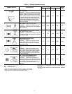
AQUASTAT: Water temperature sensing electrical
switch.
Application — Clips directly on nominal size
1
/
2
in. or
3
/
4
in. copper tubing for water temperature sensing.
Must be correctly located for proper control
operation.
Cv — Coefficient of Velocity
DX — Direct Expansion