


25
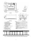
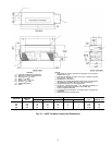
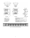
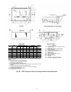
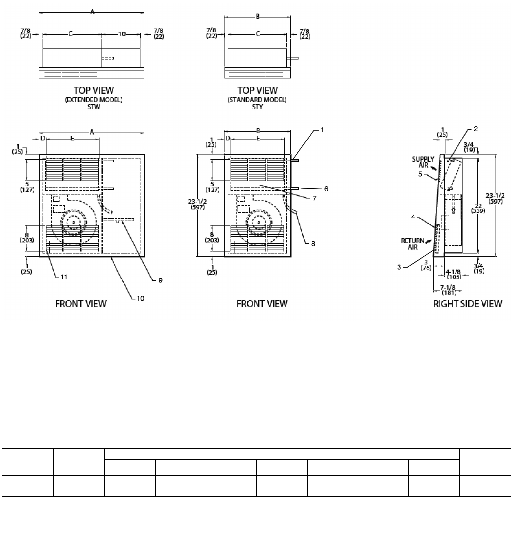
LEGEND
1— Supply Conn,
5
/
8
-in. OD
2— Air Vent,
1
/
8
-in. MPT
3— Filter
4— Return Air Grille, Stamped
5— Stamped Supply Grille
6— Return Conn,
5
/
8
-in. OD
7— Removable Front Panel
8— Drain Conn,
7
/
8
-in. OD
9— Auxiliary Drain Pan
10 — Valve Compartment
11 — Junction Box
NOTES:
1. Right hand unit shown; left hand unit opposite. Coil connection
locations are ±
5
/
8
-in.
2. Front panel has an Arctic White baked finish.
3. Standard 2-row coil shown.
4. Unit size 01 has one motor, one blower; size 03 has 2 motors,
2 blowers.
5. Unit has
1
/
2
-in. flanges for mounting to wall surface.
6. Front panel hooks at top of unit, swing down and snap in at bottom
against a spring clip.
7. Not shown: 3-speed fan switch, wall plate,
1
/
2
-in. fiberglass insula-
tion on inside of casing, closed cell foam on main drain pan.
8. Dimensions shown in inches (mm).
*Unit weights are based on dry coils and minimum rows. Weights exclude packaging, valves, and other components.
UNIT SIZE
NOM
AIRFLOW
(Cfm)
DIMENSIONS (in.) QTY/UNIT UNIT
WEIGHT*
(lb)
ABCDE
Blower Motor
01 150 25
3
/
4
15
3
/
4
14 1
1
/
2
12
3
/
4
1140
03 300 39
3
/
4
29
3
/
4
28 1
15
/
16
25
7
/
8
2274
A42-4116
Fig. 22 — 42VG Furred-In Wall Unit Dimensions