


40
INSTALLATION
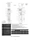
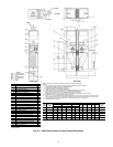
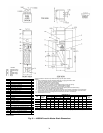
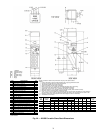
Step 1 — Place Units in Position
42C UNITS
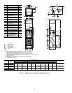
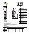
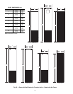
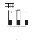
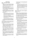
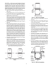
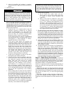
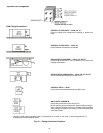
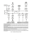
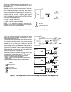
1. Select the unit location. Allow adequate space for free air
circulation, service clearances, piping and electrical
connections, and any necessary ductwork. For specific
unit dimensions, refer to Fig. 1-14. Allow clearances ac-
cording to local and national electric codes.
2. Make sure ceiling is able to support the weight of the unit.
See Table 1 for nominal unit weight.
3. Ensure bottom panel has been removed from 42CG, CK
units with mounting holes. When unit is lifted, access to
the 0.375-in. mounting holes is through the bottom of the
unit. Hanger rods and fasteners and other required hard-
ware must be field-supplied.
4. Move unit into position. Ensure unit is level or pitched
towards drain to ensure proper drainage and operation.
Pitch of suspended unit can change after coil is filled;
recheck after filling coil.
5. Mounting unit:
a. Use rods and fasteners to suspend the unit at the
factory-provided mounting holes with rubber
grommets on the top of the unit on 42CG, CK
units. Reach into unit and attach unit to the ceiling
using the 0.375-in. mounting holes (4) in top
panel; do not use any other locations.
b. Use rods and fasteners to suspend the unit at the
factory-provided 0.375-in. hanger slots (4) with
rubber grommets on the top of the unit on the
42CA, CE, and CF units.
NOTE: The four mounting holes and hanger slots
with rubber grommets are NOT for balancing unit.
6. 42CA and 42CF units without plenums and 42CE and CF
with bottom inlet may be installed in noncombustible
areas only.
NOTE: The installation of horizontal concealed units must
meet the requirements of the National Fire Protection Associa-
tion (NFPA) Standard 90A or 90B concerning the use of con-
cealed ceiling space as return-air plenums.
42V UNITS
1. Select the unit location. Allow adequate space for free air
circulation, service clearances, piping and electrical
connections, and any necessary ductwork. For specific
unit dimensions, refer to the submittals. Allow clearances
according to local and national electric codes.
2. Make sure the floor is able to support the weight of the
unit. See Table 2 for nominal unit weight.
3. Ensure wall behind unit is smooth and plumb; if
necessary, install furring strips on walls with irregular
surfaces or mullions. Furring strips must be positioned
behind mounting holes in unit (42VA, VB, VF units).
Fasteners, furring strips, and other seals (if required) must
be field-supplied.
4. Remove all wall and floor moldings from behind the unit.
5. Ensure 42VA top panel (under window application) and
42VB, VF front panel has been removed from unit to
obtain access to the four 0.75-in. mounting holes. Hanger
rods and fasteners and other required hardware must be
field-supplied.
6. Move unit into position. Ensure unit is level or pitched
towards drain to ensure proper drainage and operation.
Pitch of suspended unit can change after coil is filled;
recheck after filling coil.
7. Adjust 42VA, VB, VC, VE, VF units leveling legs so unit
is level. Unit must be level for proper operation and
condensate drainage.
8. Mounting unit:
a. Use rods and fasteners to suspend the unit at the
factory-provided mounting holes with rubber
grommets on the top of the unit on 42VA, VB, VF
units. Reach into unit and attach unit to the wall
using the 0.375-in. mounting holes (4) in top
panel; do not use any other locations. The four
mounting holes and hanger slots with rubber
grommets are NOT for balancing unit.
b. On 42VG unit ensure unit is placed snug within
the wall.
c. On 42VC, VE unit ensure unit is flushed against
the wall.
NOTE: For any unit without a return-air duct connection,
applicable installation codes may limit unit to installation in
single story residence only.
42D UNITS
1. Select the unit location. Allow adequate space for free air
circulation, service clearances, piping and electrical con-
nections, and any necessary ductwork. For specific unit
dimensions, refer to the submittal drawings. Allow clear-
ances according to the local and national electrical codes.
2. Be sure either the ceiling (42DA, DC, DE, and DF units)
or floor (42DD unit) is able to support the weight of the
unit. See Table 3 for nominal unit weight.
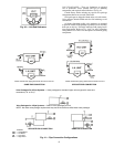
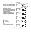
3. Move unit into position. Ensure unit is level or pitched
towards drain to ensure proper drainage and operation.
See Fig. 23-27. Pitch of suspended unit can change after
coil is filled; recheck after filling coil.
4. Mounting units to the ceiling:
a. When unit is lifted, access to the 0.375-in. mount-
ing holes is on the top panel of the unit. Hanger
rods and fasteners and other required hardware
must be field-supplied.
b. Use rods and fasteners to suspend the unit at the
factory-provided mounting holes with rubber
grommets on the top of the unit. Attach unit to the
ceiling using the 0.375-in mounting holes (4) in
top panel; do not use any other locations.
c. Use the rods and fasteners to suspend the unit at
the factory-provided 0.375-in. hanger slots (4)
with the rubber grommets on the top of the unit on
the 42DA, DC, DE, and DF units.
NOTE: The four mounting holes and hanger slots
with rubber grommets are NOT for balancing unit.
d. Models 42DA and 42DC with bottom inlet may be
installed in noncombustible return spaces only.
5. Mounting units on the floor:
a. Ensure wall behind the unit is smooth and plumb;
if necessary, install furring strips on walls with
irregular surfaces or mullions. Furring strips must
be positioned behind mounting holes on 42DD
units. Fasteners, furring strips, and other seals (if
required) must be field-supplied.
b. If the unit has leveling legs, adjust them correctly
to level the unit.
6. Protect units from damage caused by jobsite debris. Do
not allow foreign material to fall in unit drain pan.
Prevent dust and debris from being deposited on motor or
fan wheels.