


5
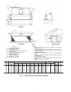
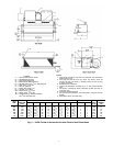
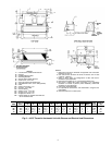
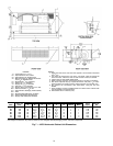
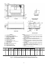
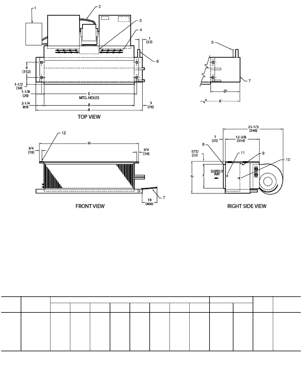
LEGEND
1—Junction Box (remote mount)
2—Flexible Metal Conduit
3 — Strip Heater High Limit
4 — Electric Strip Heater Element
5 — Tell-Tale Drain Conn,
5
/
8
-in. OD (optional)
6—Drain Conn,
7
/
8
-in. OD
7—Drip Lip (optional)
8—Supply Duct Collar, 1-in.
9—Air Vent,
1
/
8
-in. MPT
10 — Return Conn,
5
/
8
-in. OD
11 — Supply Conn,
5
/
8
-in. OD
12 — Hanger Slots (4), Rubber Grommet
has
3
/
8
-in. Diameter Hole
NOTES:
1. Right hand unit shown; left hand unit opposite. Coil connection
locations are ±
5
/
8
-in.
2. Unit sizes 02 and 03 have one motor, one blower; sizes 04
through 08 have one motor, 2 blowers; sizes 10 and 12 have
2 motors, 4 blowers.
3. Standard 3-row coil shown.
4. Overall unit dimension increases by 4 in. with optional electric
heat.
5. Not shown: 3-speed fan switch; wall plate, closed cell foam on
main drain pan.
6. Units have galvanized finish.
7. For optional coil connections, view 42CA-203-1 using the Fan Coil
Builder.
8. Dimensions shown in inches (mm).
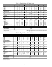
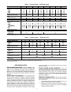
*Unit weights are based on dry coils and minimum rows. Weights exclude packaging, valves, and other components.
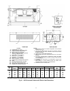
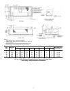
UNIT
SIZE
NOM
AIRFLOW
(Cfm)
DIMENSIONS (in.) QTY/UNIT FACE
AREA
(sq ft)
UNIT
WEIGHT*
(lb)
AA’BD’E F GH
Blower Motor
02 200 21
1
/
4
31
1
/
4
16 13 18
1
/
4
6
1
/
4
8
3
/
4
19
3
/
4
1 1 0.83 38
03 300 25
1
/
4
36
1
/
4
20 14 22
1
/
4
6
1
/
4
8
3
/
4
23
3
/
4
1 1 1.08 41
04 400 31
1
/
4
43
1
/
4
26 15 28
1
/
4
6
1
/
4
8
3
/
4
29
3
/
4
2 1 1.35 51
06 600 36
1
/
4
43
1
/
4
31 10 33
1
/
4
7
1
/
2
10 34
3
/
4
2 1 1.88 61
08 800 43
1
/
4
57
1
/
4
38 17 40
1
/
4
7
1
/
2
10 41
3
/
4
2 1 2.31 66
10 1000 57
1
/
4
65
1
/
4
52 11 54
1
/
4
7
1
/
2
10 55
3
/
4
4 2 3.16 97
12 1200 65
1
/
4
75
1
/
4
60 13 62
1
/
4
7
1
/
2
10 63
3
/
4
4 2 3.65 109
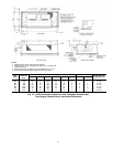
Fig. 2 — 42CA Furred-In Horizontal Unit with Electric Heat Dimensions
a42-4100.eps