


8
A
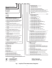
[2032]
[2173]
[2236]
[2242]
[356]
[1270]
[4780]
[4002]
[3422]
B
[3048]
[2769]
[80]
[863]
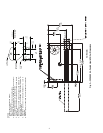
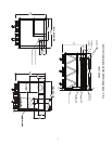
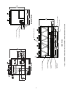
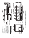
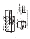
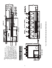
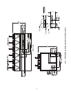
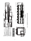
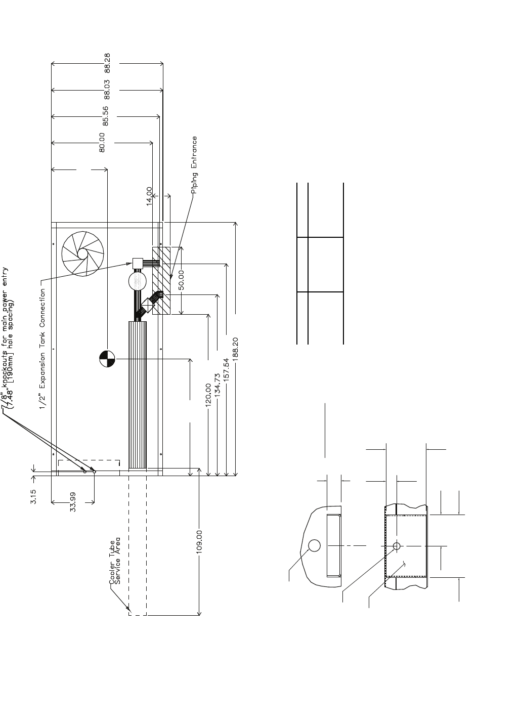
NOTES:
1. Unit must have clearances as follows:
Top — Do not restrict
Sides and Ends — 6 ft (1.8 m) from solid surface.
2. Temperature relief devices are located on liquid line and economizer assem-
blies and have
1
/
4
-in. flare connection.
3.
3
/
8
-in. NPT vents and drains located in each cooler head at each end of cooler.
4. Drawing depicts unit with single-point power and standard two-pass cooler.
Refer to the Packaged Chiller Builder program for other configurations.
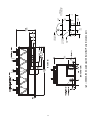
5. Dimensions are shown in inches. Dimensions in [ ] are in millimeters.
6. Allow 8 ft (2.4 m) on either side of unit for condenser coil removal.
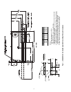
30XA UNIT A B
090 44.11 [1120] 86.93 [2208]
100 44.11 [1120] 87.22 [2215]
110 44.11 [1120] 87.62 [2226]
120 44.11 [1120] 87.12 [2213]
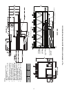
a30-4404
3.93
7.88
[200]
DETAIL "A"
MOUNTING PLATE
CONTACT SURFACE
TYPICAL 4 PLACES
[100]
MOUNTING HOLE
0.875 DIA.[22.2]
MOUNTING
PLATE
1.50 DIA. [38.1]
RIGGING HOLE
[127]
5.0
[33]
1.31
1.75
[44]
TOP VIEW
Fig. 4 — 30XA090-120 Air-Cooled Liquid Chiller with Pump Dimensions