


41
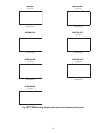
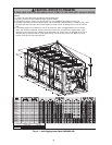
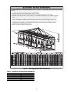
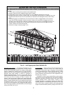
RIGGING UNIT (See Fig. 16-18) — The 30XA080-500 units
are designed for overhead rigging and it is important that this
method be used. Holes are provided in frame base channels,
marked for rigging (see rigging label on unit). Field-supplied
shackles are required to facilitate lifting. Secure the shackles
to the base rails at the points noted on the rigging label. See
Table 2 for the number of lifting points for each unit.
Do not use a forklift truck to move the units.
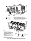
Use spreader bars to keep cables or chains clear of unit sides.
As further protection plywood sheets may be placed against
sides of unit, behind cables or chains. Run cables or chains to a
central suspension point so that angle from horizontal is not less
than 45 degrees. Raise and set unit down carefully.
See Fig. 16-18 for rigging centers of gravity.
For shipping, some domestic units and all export units are
mounted on a wooden skid under entire base of unit. Skid can
be removed before unit is moved to installation site. Lift the
unit from above to remove skid. See Fig. 16-18 for rigging
center of gravity. On export units, the top skid can be used as
the spreader bars. If the unit was shipped with a shipping bag,
the bag must be removed to gain access to the rigging holes in
the base rail.
If overhead rigging is not available, the unit can be moved
on rollers or dragged. When unit is moved on rollers, the unit
skid, if equipped, must be removed. To lift the unit, use jacks at
the rigging points. Use a minimum number of rollers to distrib-
ute the load such that the rollers are no more than 6 ft (1.8 m)
apart. If the unit is to be dragged, lift the unit as described
above, and place unit on a pad. Apply moving force to the pad,
and not the unit. When in its final location, raise the unit and
remove the pad. If the unit was shipped with coil protection, it
must be removed before start-up. The shipping bag for export
units must be removed before start-up.
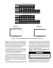
Step 3 — Cooler Fluid and Drain Piping Con-
nections —
See Fig. 19-22 for piping applications.
GENERAL — The factory-installed victaulic connections al-
low clamp-on connection of water lines to the coolers in all
30XA units. A flow sensor is factory-installed in the side of the
entering fluid nozzle. See Fig. 23. See Table 3 for 30XA unit
operating range. See Fig. 20 for cooler option dimensions.
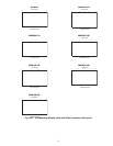
DUAL PUMP UNITS — ENGLISH
DUAL PUMP UNITS — SI
*Condenser Coil: Copper Fins/Copper Tubing.
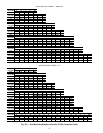
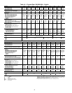
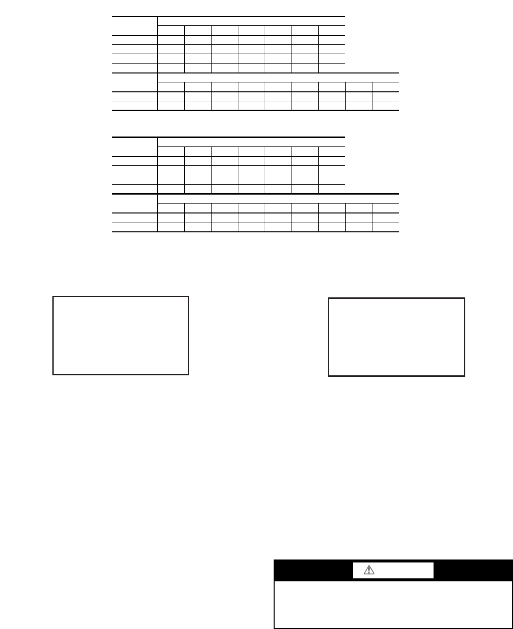
30XA
UNIT SIZE
MOUNTING WEIGHT (lb) — Cu/Cu*
ABCDEFTotal
090 1394 3347 1369 1093 2330 1392 10,924
100 1420 3409 1406 1117 23821418 11,151
110 1433 3452 1428 1139 2416 1424 11,291
120 1467 3491 1430 1142 2449 1458 11,436
30XA
UNIT SIZE
MOUNTING WEIGHT (lb) — Cu/Cu*
ABCDEFGHTotal
140 2188 1735 2012 1889 1273 1004 1876 1990 13,966
160 2242 1762 2029 1919 1299 1019 1896 2043 14,209
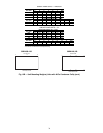
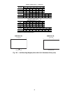
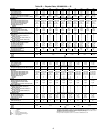
30XA
UNIT SIZE
MOUNTING WEIGHT (kg) — Cu/Cu*
ABCDEFTotal
090 632 1518 621 496 1057 631 4955
100 644 1546 638 507 1080 643 5058
110 650 1566 648 517 1096 646 5122
120 665 1583 649 518 1111 661 5187
30XA
UNIT SIZE
MOUNTING WEIGHT (kg) — Cu/Cu*
ABCDEFGHTotal
140 992 787 913 857 577 455 851 903 6335
160 1017 799 921 871 589 462 860 927 6445
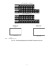
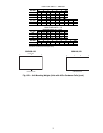
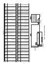
30XA090-120
30XA140,160
Fig. 15C — Unit Mounting Weights (Units with Cu/Cu Condenser Coils) (cont)
a30-4420
a30-4421
A
BC
F
E
D
COOLER SIDE
COMPRESSOR SIDE
ABCD
HGFE
COOLER
SIDE
COMPRESSOR SIDE
CAUTION
Remove the chilled water flow switch, entering and leaving
water thermistors before welding connecting piping. Rein-
stall flow switch and thermistors after welding is complete.
Failure to remove these devices may cause unit damage.