


2
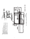
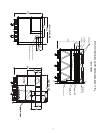
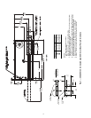
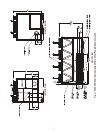
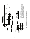
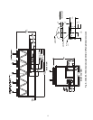
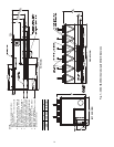
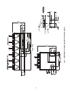
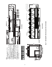
Step 2 — Place, Mount, and Rig the Unit —
When considering a location for the unit, be sure to consult
NEC (National Electrical Code, U.S.A.) and/or local code
requirements. Allow sufficient space for airflow, wiring, pip-
ing, and service. See Fig. 2-14.
NOTE: To facilitate refrigerant vent piping, all units have fus-
ible plugs with
1
/
4
in. SAE (Society of Automotive Engineers)
flares and pressure reliefs with
3
/
4
in. NPT fittings (if required
by local codes).
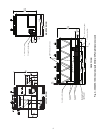
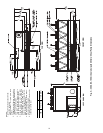
PLACING UNIT — Locate the unit so that the condenser
airflow is unrestricted both above and on the sides of the unit.
Airflow and service clearances are 6 ft (1.8 m) around the unit.
Acceptable clearance on the sides or ends without control boxes
can be reduced to 3 ft (1 m) without sacrificing performance as
long as the remaining three sides are unrestricted. Acceptable
clearance on the side with a control box can be reduced to 4 ft
(1.3 m) due to NEC regulations, without sacrificing performance
as long as the remaining three sides are unrestricted. Provide am-
ple room for servicing and removing the cooler. See Fig. 2-14 for
required clearances. Local codes for clearances take precedence
over the manufacturer’s recommendations when local codes call
for greater clearances.
If multiple units are installed at the same site, a separation of
10 ft (3 m) between the sides of the machines is required to
maintain proper airflow and minimize the chances of condens-
er air recirculation.
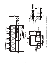
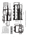
MOUNTING UNIT — The unit may be mounted on a level
pad directly on the base rails, on a raised mounting rail around
the unit, or on vibration isolation springs. For all units, ensure
placement area is strong enough to support unit operating
weight. See Tables 1A and 1B. Mounting holes are provided
for securing the unit to the pad, mounting rail or vibration
isolation springs. Bolt the unit securely to pad or rails. If vibra-
tion isolators (field-supplied) are required for a particular
installation, refer to unit weight distribution in Fig. 15A-15C to
aid in the proper selection of isolators. The 30XA units can be
mounted directly on spring isolators. Once installed, the unit
must be level to within
1
/
8
-in. per ft (1 cm per meter) along the
long axis of the oil separator. This is required for oil return to
the compressor(s).