


52
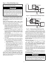
The combination valve performs the following functions:
• drip-tight shut-off valve
• spring closure design with a non-slam check valve
• flow-throttling valve
When facing the cooler side of unit, the inlet (return) water
connection is on the bottom. The outlet (supply) water connec-
tion is on the top. The inlet is connected to the suction guide/
strainer of the pump via a Victaulic-type connection. The cool-
er supply has water-side Victaulic-type connections (follow
connection directions as provided by the coupling manufactur-
er). Provide proper support for the piping. If accessory security
grilles have been added, holes must be cut in the grilles for
field piping and insulation.
There is a factory supplied, insulated 45-degree elbow pipe
and a victaulic coupling shipped with units ordered with a
hydronic pump package. Before starting field piping, use the
victaulic coupling to connect this elbow pipe to the outlet of the
combination valve.
The suction guide/strainer is shipped from the factory with a
run-in screen. This screen is a temporary device used during
the start-up/clean-up process of the chilled water circuit to
prevent construction debris from damaging the pump or
internal tubes of the cooler. After all debris has been removed
or a maximum of 24 running hours the temporary screen must
be removed. See the Start-Up, Controls, Operation and
Troubleshooting guide for further information.
NOTE: It is required that a 20 mesh field-supplied strainer be
installed in the inlet piping to the cooler on open loop systems.
A
3
/
4
in. NPT fitting is installed in the inlet piping of the
pump for connection to an expansion tank. Install the tank in
accordance with the manufacturer's instructions.
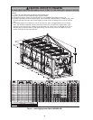
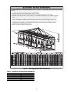
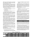
Figures 25 and 26 illustrate typical single and dual pump
packages.
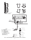
Three drain connections are provided and are located at
leaving water (supply) end of cooler, pump volute, and the
suction guide. See Fig. 2-14 for connection location. Insulate
the drain piping (in the same manner as the chilled water pip-
ing) for at least 12 in. (305 mm) from the cooler.
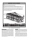
UNITS WITHOUT HYDRONIC PUMP PACKAGE — When
facing the cooler side of the unit, the inlet (return) water connec-
tion is on the bottom. It is required that a field-supplied strainer
with a minimum size of 20 mesh be installed within 10 ft
(3.05 m) of the cooler inlet to prevent debris from damaging
internal tubes of the cooler. The outlet (supply) water connection
is on the top. The cooler has water-side victaulic-type connec-
tions (follow connection directions as provided by the coupling
manufacturer). Provide proper support for the piping. If accesso-
ry security grilles have been added, holes must be cut in the
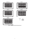
grilles for field piping and insulation. See Fig. 28 for a typical
piping diagram of a 30XA unit without a hydronic pump pack-
age.
A drain connection is located at the leaving water (supply)
end of cooler. See Fig. 2-14 for connection location. Insulate
the drain piping (in the same manner as the chilled water
piping) for at least 12 in. (305 mm) from the unit.
DUAL CHILLER CONTROL — the Co mfort Link™ con-
troller allows 2 chillers (piped in parallel or series) to operate as a
single chilled water plant with standard control functions
coordinated through the master chiller controller. This standard
ComfortLink feature requires a communication link between the
2 chillers.
There are several advantages to this type of control:
• redundancy (multiple circuits)
• better low load control, (lower tonnage capability)
• lower rigging lift weights (2 machines rather than 1 large
machine)
• chiller lead-lag operation (evens the wear between the
two machines)
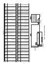
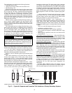
Dual Chiller Leaving Water Sensor
—If the dual chiller algo-
rithm is used, and the machines are installed in parallel, a dual
chilled water sensor must be installed for each module. Install
the well in the common leaving water header. See Fig. 21. The
series dual chiller application is shown in Fig. 22.
Parallel Dual Chiller Operation
— Parallel chiller operation
is the recommended option for dual chiller control. In this case,
each chiller must control its own dedicated pump or isolation
valve. Balancing valves are recommended to insure proper
flow in each chiller. Two field-supplied and installed dual chill-
er leaving water temperature sensors are required, one for each
module for this function to operate properly.
Consider adding additional isolation valves to isolate each
chiller to allow for service on a machine, and still allow for par-
tial capacity from the other chiller. See Fig 21.
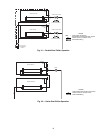
Series Dual Chiller Operation
— Series chiller operation is an
alternate control method supported by the ComfortLink™
control system. Certain applications might require that the two
chillers be connected in series. For nominal 10º F (5.6º C) cool-
er ranges, use the minus 1 pass cooler arrangements to reduce
the fluid-side pressure drop. Use the standard cooler pass
arrangement for low flow, high cooler temperature rise
applications.
Consider adding additional piping and isolation valves to
isolate each chiller to allow for service on a machine, and still
allow for partial capacity from the other chiller. See Fig. 22.
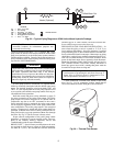
CAUTION
The suction guide/strainer is shipped from the factory with
a run-in screen. This temporary screen must be removed
after all debris has been removed or a maximum of 24 run-
ning hours. Failure to remove the temporary screen may
result in damage to the pump or cooler.
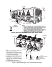
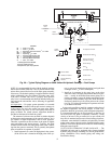
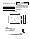
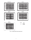
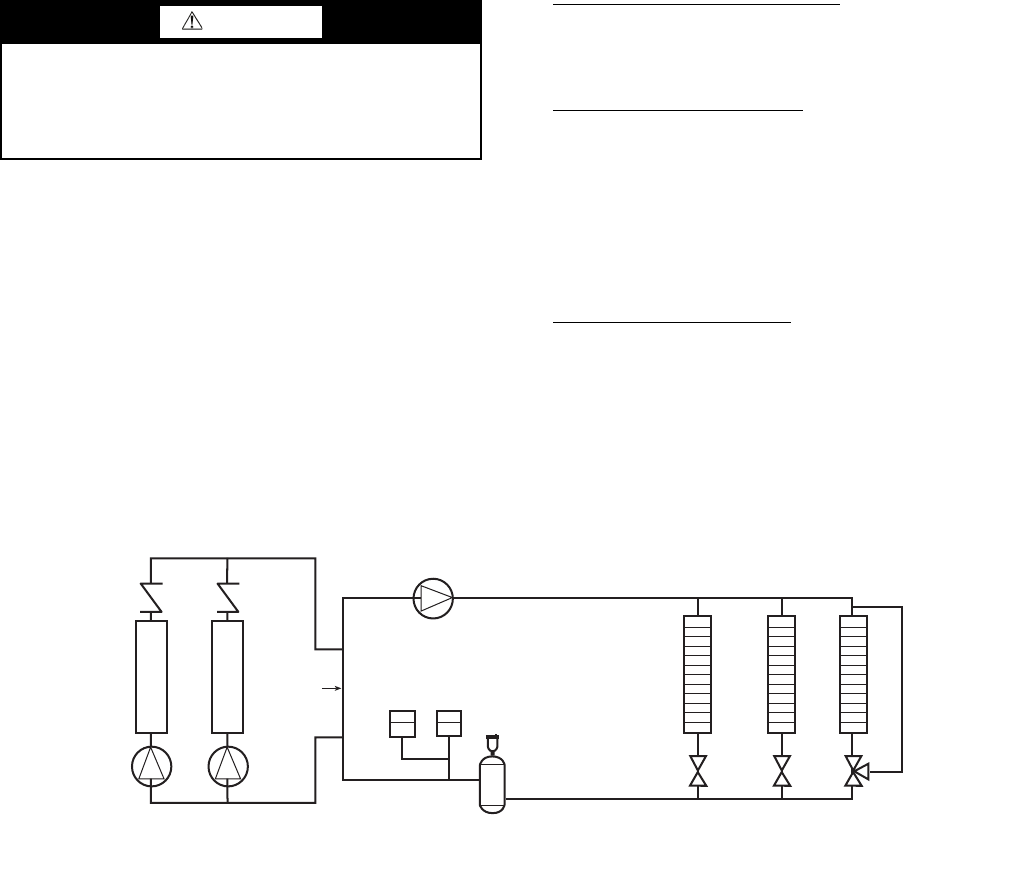
Distribution Pump
Expansion
Tank(s)
Air Separator
with Vent
Decoupler
Chiller 1
Chiller 2
Zone 1
Zone 2
Zone 3
NOTE: Expansion tanks for 30XA hydronic kits must be installed for chillers piped in parallel in the primary water loop.
Fig. 27 — Typical Air Separator and Expansion Tank Location on Primary-Secondary Systems
a30-4002