


45
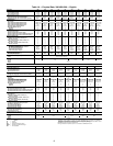
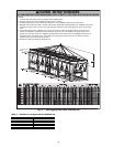
Table 2 — Number of Lifting Points for 30XA080-500
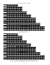
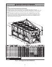
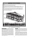
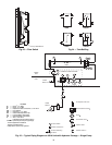
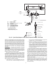
ALL PANELS MUST BE IN PLACE WHEN RIGGING. DO NOT ATTEMPT TO FORK THESE UNITS IF NO SKID IS SUPPLIED.
CAUTION - NOTICE TO RIGGERS:
NOTES:
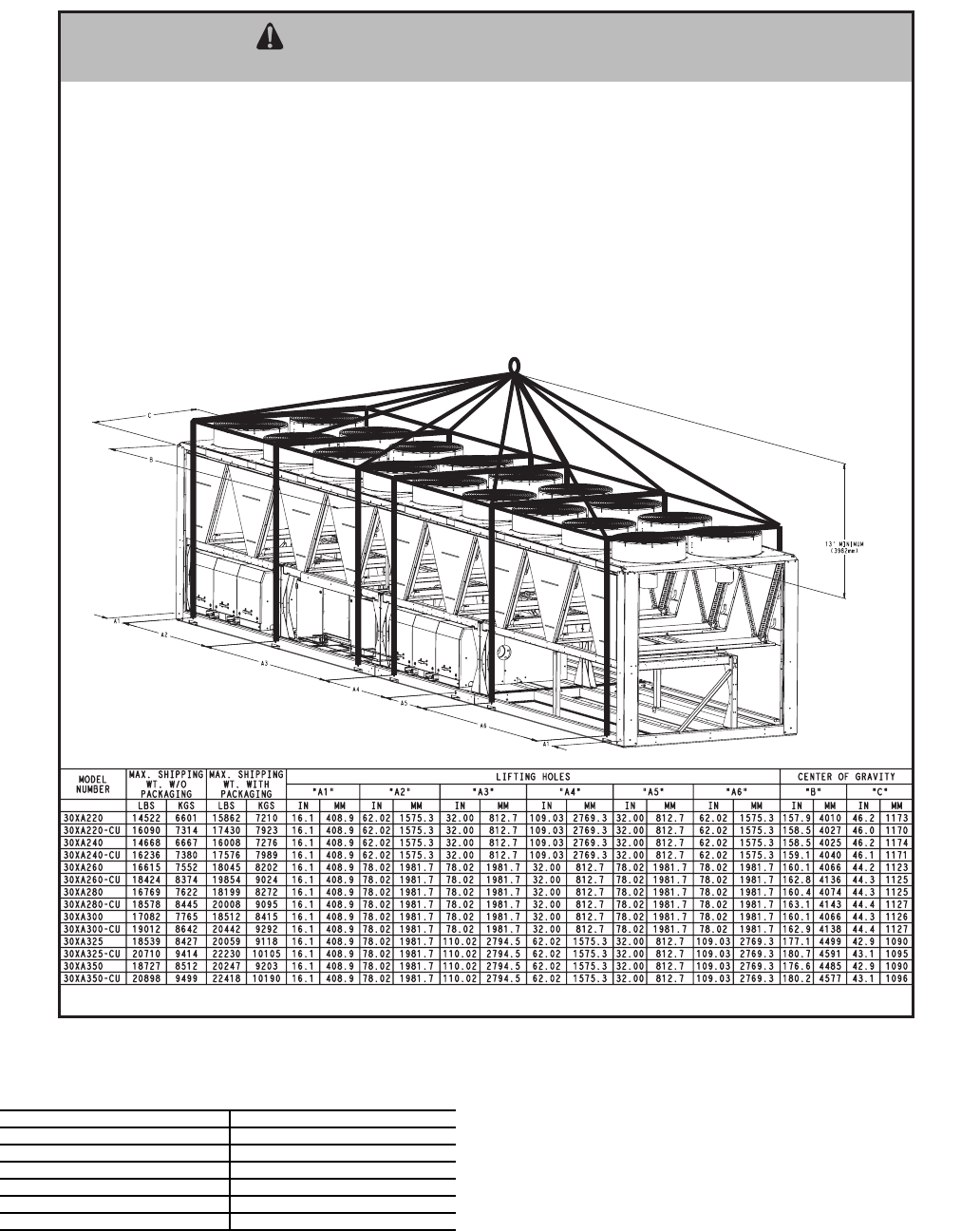
1. 1.50 dia. (38.1mm) lifting holes provided for field supplied clevis.
2. Rig with a minimum of 25 ft (7620mm) length chains or cables.
3. If central lifting point is used, it must be a minimum of 13 ft. (3962mm) above the top of the unit.
4. Spreader bars made from steel or double nailed, and notched 2x6's approximately 8 ft. (2438mm) long, must
be placed just above the top of the unit (and stacks) to reduce the risk of da
mage to the top of the unit and
coils.
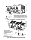
5. If overhead rigging is not available, the unit can be moved on rollers or dragged. When unit is moved on
rollers, the unit skid, if equipped, must be removed. To lift the unit, use jacks at the rigging points. Use a
minimum of one roller every 6 ft. (1829mm) to distribute the load. If the unit is to be dragged, lift the unit as
described above, and place unit on a pad. Apply moving force to the pad, not the unit. When in its fina
l
location, raise the unit and remove the pad.
6. Check bill of lading for shipping weight of unit.
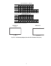
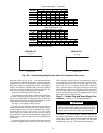
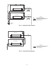
Fig. 17 — Unit Rigging Label Detail 30XA220-350
a30-4428
30XA UNIT SIZE NUMBER OF LIFTING POINTS
080 4
090-120 6
140, 160 8
180, 200 10
220-400 12
450, 500 14