


51
NOTE: It is recommended for units with the hydronic package
that an inlet isolation (shut-off) valve be placed exterior to the
unit to allow removal and service of the entire pump assembly,
if necessary. The hydronic package is supplied from the factory
with a combination valve for isolation of leaving water. Also,
if the unit is isolated with valves, a properly sized pressure
relief valve is recommended and should be installed in the pip-
ing between the unit and the valves, following all applicable
local codes.
Air Separation
— For proper system operation, it is essential
that water loops be installed with proper means to manage air
in the system. Free air in the system can cause noise, reduce
terminal output, stop flow, or even cause pump failure due to
pump cavitation. For closed systems, equipment should be
provided to eliminate all air from the system.
The amount of air that water can hold in solution depends
on the pressure and temperature of the water/air mixture. Air is
less soluble at higher temperatures and at lower pressures.
Therefore, separation can best be done at the point of highest
water temperature and lowest pressure. Typically, this point
would be on the suction side of the pump as the water is return-
ing from the system or terminals. This is generally the optimal
place to install an air separator, if possible.
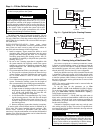
1. Install automatic air vents at all high points in the system.
(If the 30XA unit is located at the high point of the sys-
tem, a vent can be installed on the piping leaving the heat
exchanger on the
1
/
4
in. NPT female port.)
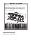
2. Install an air separator in the water loop, at the place
where the water is at higher temperatures and lower pres-
sures — usually in the chilled water return piping. On a
primary-secondary system, the highest temperature water
is normally in the secondary loop, close to the decoupler.
Preference should be given to that point on the system
(see Fig. 27). In-line or centrifugal air separators are read-
ily available in the field.
It may not be possible to install air separators at the place of
the highest temperature and lowest pressure. In such cases,
preference should be given to the points of highest temperature.
It is important that the pipe be sized correctly so that free air
can be moved to the point of separation. Generally, a water
velocity of at least 2 feet per second (0.6 m per second) will
keep free air entrained and prevent it from forming air pockets.
Automatic vents should be installed at all physically elevated
points in the system so that air can be eliminated during system
operation. Provisions should also be made for manual venting
during the water loop fill.
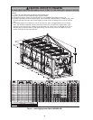
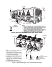
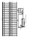
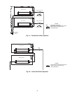
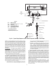
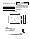
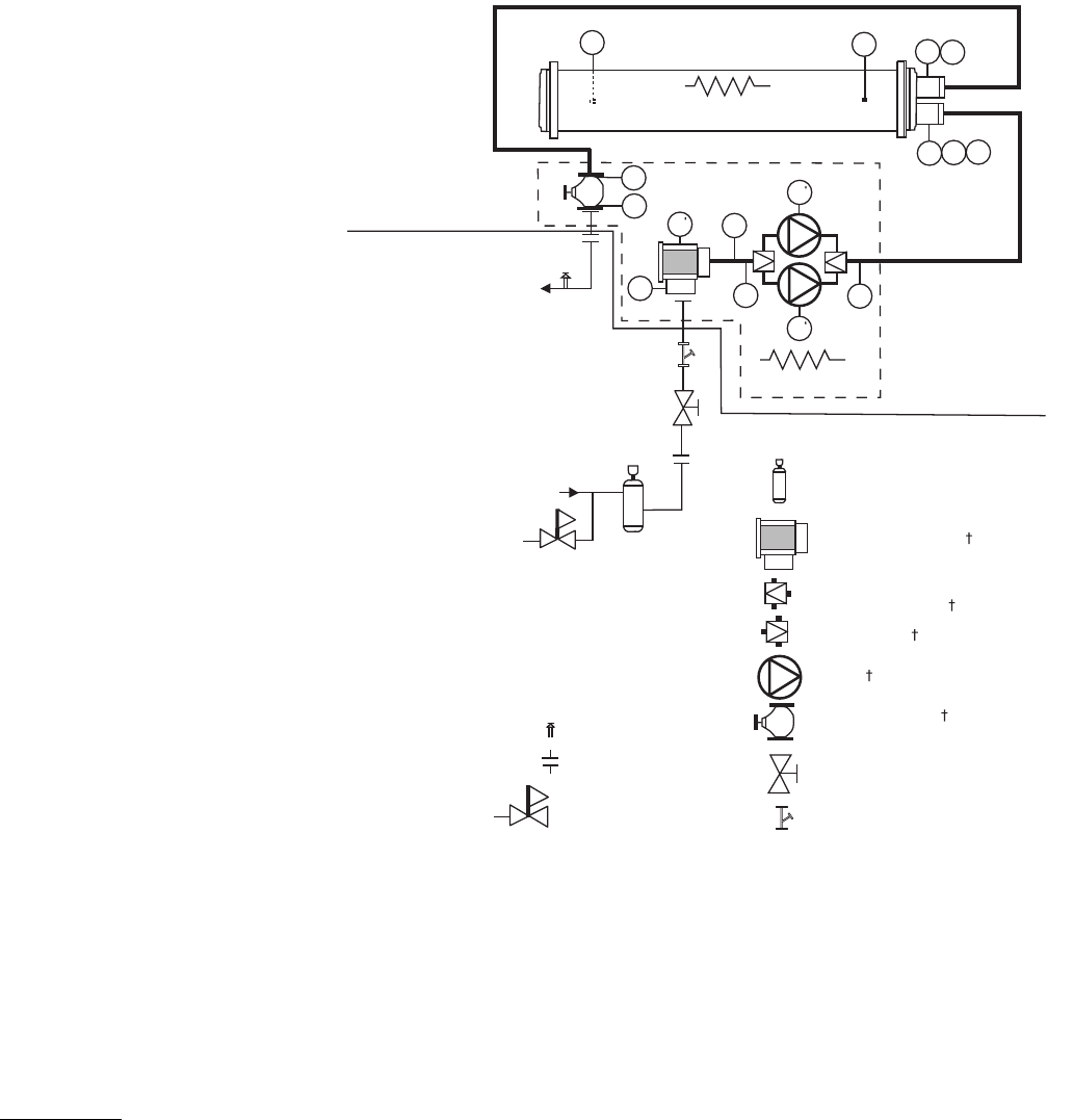
UNITS WITH HYDRONIC PUMP PACKAGE — The
30XA090-160 units can be equipped with a factory-installed
hydronic pump package consisting of a suction guide/strainer,
pump, combination valve, internal piping and wiring con-
nected at the factory.
PT
PT
T1
PP
PP
D
D
V
D
PT
PT
Chilled
Water Out
Heater
Heater
E
D
PT
Air Separator with Vent*
Strainer/Suction Guide
Reverse Flow Check
Valve/Service Valve
Pump
Service Valve
Combination Valve
Isolation Valve*
Pressure Reducing
Fill Valve*
Flexible Connections*
Pressure Relief*
Chilled
Water In
HYDRONIC PUMP PACKAGE
INSIDE
UNIT
OUTSIDE
UNIT
20 Mesh Stainer**
T2
FS
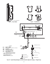
LEGEND
*Field-supplied and installed.
†Factory-installed option.
**Required for open loop systems.
D—Drain,
3
/
4
-in. NPT
D — Drain,
1
/
4
-in. NPT
E—Expansion Tank Connection,
3
/
4
-in. NPT
FS — Flow Switch
PP — Pipe Plug,
1
/
4
-in. NPT
PT — Pressure/Temperature Tap
T1 — Leaving Water Thermistor
T2 — Entering Water Thermistor
V—Vent,
1
/
4
-in. NPT
Fig. 26 — Typical Piping Diagram on 30XA Units with Hydronic Package — Dual Pumps
a30-4415