


76
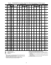
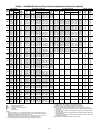
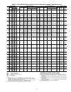
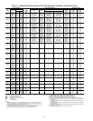
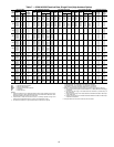
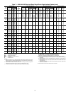
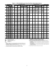
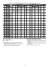
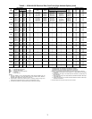
Table 11 — Pump Electrical Data
FLA — Full Load Amps
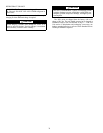
Table 12 — CCN Communication Bus Wiring
4. The RJ14 CCN connector on TB3 can also be used, but is
only intended for temporary connection (for example, a
laptop computer running service tool).
NON-CCN COMMUNICATION WIRING — The 30XA units
offer several non-CCN translators. Refer to the separate installa-
tion instructions for additional wiring steps.
FIELD CONTROL OPTION WIRING — Install field con-
trol wiring options. Some options, such as 4 to 20 mA demand
limit that requires the energy management module, may
require that accessories be installed first (if not factory
installed) for terminal connections.
DUAL CHILLER LEAVING WATER SENSOR — If the dual
chiller algorithm is used and the machines are installed in par-
allel, an additional chilled water sensor must be installed for
each chiller. Install the wells in the common leaving water
header. See Fig 39. DO NOT relocate the chiller’s leaving
water thermistors. They must remain in place for the unit to
operate properly.
The thermistor well is a
1
/
4
in. NPT fitting for securing the
well in the piping. The piping must be drilled and tapped for
the well. Select a location that will allow for removal of the
thermistor without any restrictions.
Once the well is inserted, install the thermistors. Insert the
thermistor into the well until the o-ring reaches the well body.
Use the nut on the thermistor to secure the thermistor in place.
Once the thermistor is in place, it is recommended that a
thermistor wire loop be made and secured with a wire tie to the
chilled water pipe. See Fig. 39.
For dual chiller control a CCN bus must be connected
between the two modules. See the Carrier Comfort Network
Communication Bus Wiring section for additional information.
PUMP
HP
UNIT VOLTAGE
V-Hz (3 Ph)
HYDRONIC SYSTEM (SINGLE OR DUAL)
FLA (Each)
30XA
UNIT SIZE
5
230-60 11.6
090-160
200-60 12.6
460-60 5.8
575-60 4.6
380-60 7.0
7.5
230-60 17.4
090-160
200-60 18.5
460-60 8.7
575-60 7.0
380-60 10.4
10
230-60 23.0
090-160
200-60 25.0
460-60 11.5
575-60 9.2
380-60 14.0
15
230-60 34.0
090-160
200-60 36.7
460-60 17.0
575-60 14.0
380-60 21.0
MANUFACTURER
PART NUMBER
Regular Wiring Plenum Wiring
Alpha 1895 —
American A21451 A48301
Belden 8205 884421
Columbia D6451 —
Manhatten M13402 M64430
Quabik 6130 —
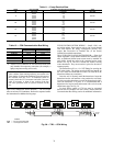
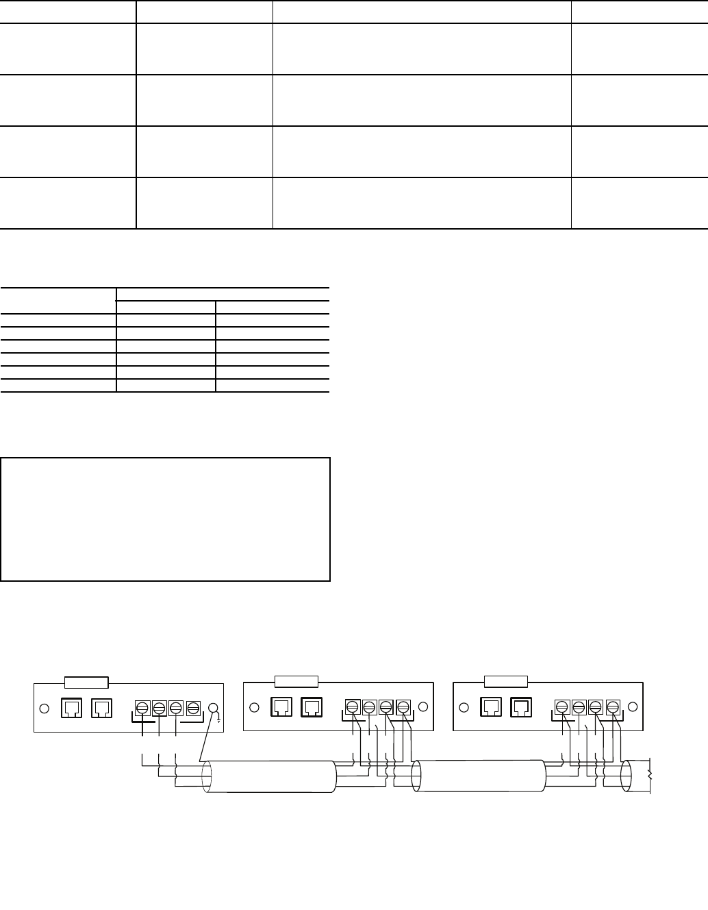
IMPORTANT: A shorted CCN bus cable will prevent
some routines from running and may prevent the unit
from starting. If abnormal conditions occur, disconnect
the machine from the CCN. If conditions return to
normal, check the CCN connector and cable. Run new
cable if necessary. A short in one section of the bus
can cause problems with all system elements on the
bus.
(+) (COM) (-) SHIELD
CCN
RED
WHT
BLK
CCNLEN
(+) (COM) (-) SHIELD
CCN
RED
WHT
BLK
CCNLEN
TO NEXT
DEVICE
(+) (COM) (-) SHIELD
CCN
RED
WHT
BLK
CCN
LEN
SHIELD
LEGEND
Fig. 38 — TB3 — CCN Wiring
CCN — Carrier Comfort Network®
LEN — Local Equipment Network
a30-4001