


56
Step 4 — Fill the Chilled Water Loop.
The chilled water pump (if equipped) is rated for 150 psig
(1034 kPa) duty. The maximum cooler fluidside pressure is
300 psig (2068 kPa). Check the pressure rating for all of the
chilled water devices installed. Do not exceed the lowest pres-
sure rated device.
WATER SYSTEM CLEANING — Proper water system
cleaning is of vital importance. Excessive particulates in the
water system can cause excessive pump seal wear, reduce or
stop flow, and cause damage of other components.
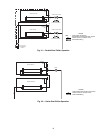
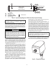
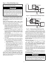
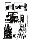
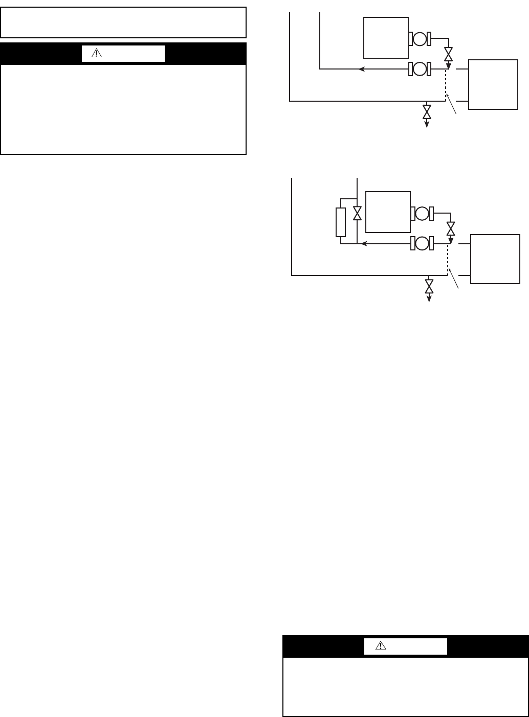
1. Install a temporary bypass around the chiller to avoid
circulating dirty water and particulates into the pump
package and chiller during the flush. Use a temporary
circulating pump during the cleaning process. Also, be
sure that there is capability to fully drain the system after
cleaning. See Fig. 31.
2. Be sure to use a cleaning agent that is compatible with
all system materials. Be especially careful if the system
contains any galvanized or aluminum components. Both
detergent-dispersant and alkaline-dispersant cleaning
agents are available.
3. It is recommended to fill the system through a water me-
ter. This provides a reference point for the future for loop
volume readings, and it also establishes the correct quan-
tity of cleaner needed in order to reach the required
concentration.
4. Use a feeder/transfer pump to mix the solution and fill the
system. Circulate the cleaning system for the length of
time recommended by the cleaning agent manufacturer.
a. After cleaning, drain the cleaning fluid and flush the
system with fresh water.
b. A slight amount of cleaning residue in the system can
help keep the desired, slightly alkaline, water pH of 8
to 9. Avoid a pH greater than 10, since this will
adversely affect pump seal components.
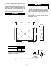
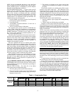
c. A side stream filter is recommended (see Fig. 32 dur-
ing the cleaning process). Filter side flow rate should
be enough to filter the entire water volume every 3 to
4 hours. Change filters as often as necessary during
the cleaning process.
d. Remove temporary bypass when cleaning is complete.
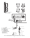
A suction guide with an internal strainer is standard on all
30XA units with factory-installed hydronic packages. This
strainer allows removal of particulates from the chilled
water loop. Using the combination valve and the field-installed
isolation valve at the inlet, the strainer can be isolated from the
chilled water loop to be cleaned.
The Carrier ComfortLink™ controls provided have a built-
in feature to remind building owners or operators to clean the
strainer at a pre-set time interval. Properly installed, cleaned
and maintained systems will rarely need the strainer cleaned
after the initial fill. This time interval is user-configurable.
Ideally, the chilled water loop will be cleaned before the unit
is connected. If the run-in screen is left in the suction guide/
strainer, it is recommended that the Service Maintenance be set
to alert the operator within 24 hours of start-up to be sure that
the run-in screen in the suction guide/strainer is removed after
24 hours of operation.
NOTE: The suction guide/strainer must be removed after the
first 24 hours of operation.
To set the time for the parameter, go to Time
Clock
MCFG
W.FIL in the handheld Navigator™ display.
To set the time for the parameter with the Touch Pilot™ dis-
play, go to Main Menu
Service
MAINTCFG
wfilter_c.
Values for this item are input in days.
WATER TREATMENT — Fill the fluid loop with water (or
brine) and a corrosion-resistant inhibitor suitable for the water
of the area. Consult the local water treatment specialist for
characteristics of system water and a recommended inhibitor
for the cooler fluid loop.
Untreated or improperly treated water may result in corro-
sion, scaling, erosion, or algae. The services of a qualified wa-
ter treatment specialist should be obtained to develop and mon-
itor a treatment program.
IMPORTANT: Before starting unit, be sure all of the
air has been purged from the system.
WARNING
In low ambient (below 32 F [0° C]) and/or low leaving
fluid temperature applications (below 40 F [4.4° C]), a suit-
able antifreeze solution of the proper concentration for the
specific operating conditions must be used as the fluid cir-
culated through the cooler to prevent freezing and damage
to the system. Failure to operate the system with an anti-
freeze solution of the proper concentration will void the
warranty should damage result from freezing.
CAUTION
Water must be within design flow limits, clean, and treated
to ensure proper chiller performance and reduce the poten-
tial of tube damage due to corrosion, scaling, erosion, and
algae. Carrier assumes no responsibility for chiller damage
resulting from untreated or improperly treated water.
x
x
DILUTED
CLEANING
AGENT
SYSTEM
POT FEEDER AND
TRANSFER PUMP
30XA UNIT
TEMPORARY
BYPASS
TEMPORARY
PUMP
TO DRAIN
Fig. 31 — Typical Set Up for Cleaning Process
a30-4411
x
x
DILUTED
CLEANING
AGENT
SYSTEM
SIDE
STREAM
FILTER
POT FEEDER AND
TRANSFER PUMP
30XA UNIT
TEMPORARY
PUMP
TEMPORARY
BYPASS
TO DRAIN
Fig. 32 — Cleaning Using a Side Stream Filter
a30-4412