


62
Step 5 — Make Electrical Connections
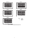
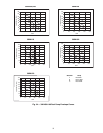
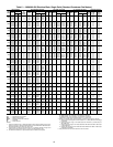
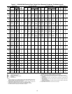
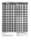
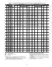
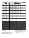
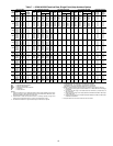
POWER SUPPLY — The electrical characteristics of the
available power supply must agree with the unit nameplate
rating. Supply voltage must be within the limits shown. See
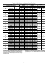
Tables 5-11 for electrical and configuration data.
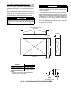
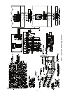
FIELD POWER CONNECTIONS (See Fig. 37) — All power
wiring must comply with applicable local and national codes.
Install field-supplied, branch circuit fused disconnect(s) of a
type that can be locked off or open. Disconnect(s) must be locat-
ed within sight and readily accessible from the unit in compli-
ance with NEC Article 440-14 (U.S.A.). See Tables 5-11 for
unit electrical data.
Maximum wire size that the unit terminal block or non-
fused disconnect will accept is 500 kcmil.
POWER WIRING — All power wiring must comply with ap-
plicable local and national codes. Install field-supplied branch
circuit fused disconnect per NEC of a type that can be locked
OFF or OPEN. Disconnect must be within sight and readily ac-
cessible from the unit in compliance with NEC Article 440-14.
In the power box,
7
/
8
in. holes are provided for power entry.
The holes will need to bee enlarged to accept the appropriate
conduit. NEC also requires all conduits from a conditioned
space to the power box(es) be sealed to prevent airflow and
moisture into the control box.
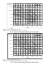
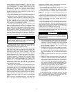
The 30XA units require 1 or 2 power supplies, depending
on the unit and circuit voltage. See Tables 5-8 for chiller elec-
trical data. Cooler and pump heaters, if factory-installed, are
wired in the control circuit. Heaters on chillers with the option-
al control transformer will be capable of operation only when
the main power supply to the chiller is on. On chillers with sep-
arate control power, the heaters are capable of operation when-
ever the control power is supplied.
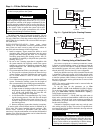
FIELD CONTROL POWER CONNECTIONS (See
Fig. 37) — All units require 115-1-60 control circuit power,
unless the control transformer option is installed.
Terminals TB5-1 and TB5-2 are provided for field installa-
tion of a chilled water (fluid) pump interlock (CWPI). The
chilled water (fluid) flow sensor (CWFS) is factory installed.
These devices are to be installed in series. Contacts must be
rated for dry-circuit applications capable of handling a 24-vac
at 50 mA load.
An accessory remote on-off switch can be wired into TB5-9
and TB5-10. Contacts must be rated for dry-circuit applications
capable of handling a 24-vac at 50 mA load.
Terminals 11 and 13 of TB5 are for control of the chilled
water pump 1 (PMP1) starter. Terminals 13 and 15 of TB5 are
for control of the chilled water pump 2 (PMP2) starter.
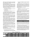
CARRIER COMFORT NETWORK
®
COMMUNICATION
BUS WIRING (See Fig. 38) — The communication bus wiring
is a shielded, 3-conductor cable with drain wire and is field
supplied and installed in the field.
The system elements are connected to the communication
bus in a daisy chain arrangement. The positive pin of each
system element communication connector must be wired to the
positive pins of the system elements on either side of it. This is
also required for the negative and signal ground pins of
each system element. Wiring connections for CCN (Carrier
Comfort Network) should be made at TB (terminal block) 3.
Consult the CCN Contractor’s Manual for further information.
See Fig. 38.
NOTE: Conductors and drain wire must be 20 AWG
(American Wire Gage) minimum stranded, tinned copper.
Individual conductors must be insulated with PVC, PVC/
nylon, vinyl, Teflon, or polyethylene. An aluminum/polyester
100% foil shield and an outer jacket of PVC, PVC/nylon,
chrome vinyl, or Teflon with a minimum operating tempera-
ture range of –4 F (–20 C) to 140 F (60 C) is required. See
Table 12 for a list of manufacturers that produce CCN bus
wiring that meet these requirements.
It is important when connecting to a CCN communication
bus that a color coding scheme be used for the entire network
to simplify the installation. It is recommended that red be used
for the signal positive, black for the signal negative, and white
for the signal ground. Use a similar scheme for cables contain-
ing different colored wires. At each system element, the shields
of its communication bus cables must be tied together. If the
communication bus is entirely within one building, the result-
ing continuous shield must be connected to a ground at one
point only. If the communication bus cable exits from one
building and enters another, the shields must be connected to
grounds at the lightning suppressor in each building where the
cable enters or exits the building (one point per building only).
To connect the unit to the network:
1. Turn off power to the control box.
2. Cut the CCN wire and strip the ends of the red (+), white
(ground), and black (–) conductors. Substitute appropri-
ate colors for different colored cables.
3. Connect the red wire to (+) terminal on TB3 of the plug,
the white wire to COM terminal, and the black wire to the
(–) terminal.
WARNING
Electrical shock can cause personal injury and death. Shut
off all power to this equipment during installation. There
may be more than one disconnect switch. Tag all discon-
nect locations to alert others not to restore power until work
is completed.
IMPORTANT: The 30XA units have a factory-installed
option available for a non-fused disconnect for unit power
supply. If the unit is equipped with this option, all field
power wiring should be made to the non-fused disconnect
since no terminal blocks are supplied.
CAUTION
Do not use interlocks or other safety device contacts
connected between TB5-9 and TB5-10 as remote on-off.
Connection of safeties or other interlocks between these
2 terminals will result in an electrical bypass if the
ENABLE-OFF-REMOTE contact switch is in the
ENABLE position. If remote on-off unit control is
required, a field-supplied relay must be installed in the unit
control box and wired as shown in Fig. 37. Failure to wire
the remote on-off as recommended may result in tube
freeze damage.