


46
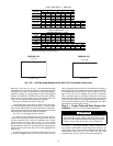
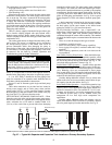
Minimum Loop Volume
— The preferred minimum loop vol-
ume is dependent on the type of application. In order to obtain
leaving water temperature stability for comfort cooling appli-
cations, a minimum of 3 gallons per ton (3.25 liters per kW) is
required on all unit sizes. For process cooling applications, ap-
plications where high stability is critical, or operation at
ambient temperatures below 32 F (0° C) is expected, the loop
volume should be increased to 6 to 10 gallons per ton (6.46 to
10.76 liters per kW) of cooling. In order to achieve this
volume, it may be necessary to add a water storage tank to the
water loop. If a storage tank is added to the system, it should be
properly vented so that the tank can be completely filled and all
air eliminated. Failure to do so could cause lack of pump stabil-
ity and poor system operation. Any storage tank that is placed
in the water loop should have internal baffles to allow thorough
mixing of the fluid. See Fig. 24.
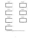
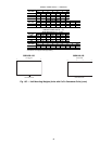
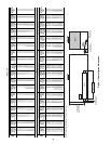
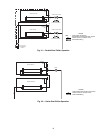
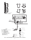
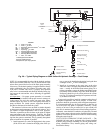
System Piping
— Proper system design and installation proce-
dures should be followed closely. The system must be
constructed with pressure tight components and thoroughly
tested for installation leaks. Factory-supplied hydronic systems
are available with single or dual (for back-up) pumps. The
factory-installed system includes all of the components above
the line in Fig. 25 and 26.
Installation of water systems should follow sound engineer-
ing practice as well as applicable local and industry standards.
Improperly designed or installed systems may cause unsatis-
factory operation and/or system failure. Consult a water
treatment specialist or appropriate literature for information
regarding filtration, water treatment, and control devices. Fig-
ures 25 and 26 show a typical installation with components that
might be installed with the hydronic package of the 30XA unit.
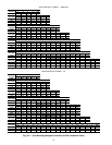
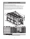
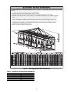
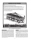
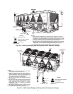
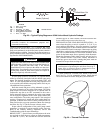
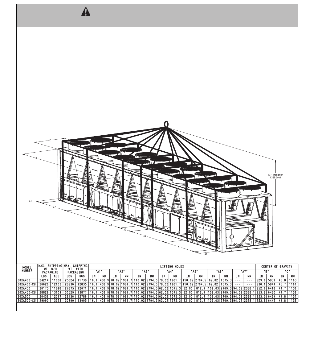
ALL PANELS MUST BE IN PLACE WHEN RIGGING. DO NOT ATTEMPT TO FORK THESE UNITS IF NO SKID IS SUPPLIED.
CAUTION - NOTICE TO RIGGERS:
NOTES:
1. 1.50 dia. (38.1mm) lifting holes provided for field supplied clevis.
2. Rig with a minimum of 25 ft (7620mm) length chains or cables.
3. If central lifting point is used, it must be a minimum of 13 ft. (3962mm) above the top of the unit.
4. Spreader bars made from steel or double nailed, and notched 2x6's approximately 8 ft. (2438mm) long, must
be placed just above the top of the unit (and stacks) to reduce the risk of da
mage to the top of the unit and
coils.
5. If overhead rigging is not available, the unit can be moved on rollers or dragged. When unit is moved on
rollers, the unit skid, if equipped, must be removed. To lift the unit, use jacks at the rigging points. Use a
minimum of one roller every 6 ft. (1829mm) to distribute the load. If the unit is to be dragged, lift the unit as
described above, and place unit on a pad. Apply moving force to the pad, not the unit. When in its fina
l
location, raise the unit and remove the pad.
6. Check bill of lading for shipping weight of unit.
Fig. 18 — Unit Rigging Label Detail 30XA400-500
a30-4428