


77
Step 6 — Install Accessories — A number of acces-
sories are available to provide the following optional features
(for details, refer to the Controls and Troubleshooting guide
shipped with the unit).
ENERGY MANAGEMENT MODULE — The energy man-
agement module is used for any of the following types of
temperature reset, demand limit and ice features:
• 4 to 20 mA inputs for cooling set point reset and capacity
limit (requires field-supplied 4 to 20 mA generator)
• 0 to 10 v output for percentage total capacity running
• 24 v discrete outputs for shutdown and running relays
• 10k space temperature input
Discrete inputs for occupancy override, demand limit
switch 2 (step 1 demand limit is wired to the base board,
requires field-supplied dry contacts), remote lockout switch
and ice done switch (requires field-supplied dry contacts).
REMOTE ENHANCED DISPLAY (OR TOUCH PILOT™
DISPLAY) — For applications where remote monitoring of
the equipment is required; the remote enhanced display (or
Touch Pilot display) provides an indoor display, capable of
monitoring any equipment on the Carrier Comfort Network
®
(CCN) bus. A CCN bus is required.
LOW AMBIENT TEMPERATURE OPERATION — If out-
door ambient operating temperatures below 32 F (0° C) are
expected, refer to separate installation instructions for low-
ambient operation using the low ambient temperature head
pressure control accessory.
MINIMUM LOAD ACCESSORY — Contact your local
Carrier representative for more details if a minimum load ac-
cessory is required for a specific application. For installation
details, refer to separate installation instructions supplied with
the accessory package.
UNIT SECURITY/PROTECTION ACCESSORIES — For
applications with unique security and/or protection require-
ments, several options are available for unit protection.
Security grilles and hail guards are available. Contact a local
Carrier representative for more details. For installation details,
refer to separate installation instructions supplied with the
accessory package.
COMMUNICATION ACCESSORIES — A number of com-
munication options are available to meet any requirement.
Contact your local Carrier representative for more details. For
installation details, refer to separate installation instructions
supplied with the accessory package.
SERVICE OPTIONS — Two accessories are available to aid
in servicing 30XA units: a ground fault convenience outlet
(GFI-CO) and a remote service port.
The GFI-CO is a convenience outlet with a 4-amp GFI
receptacle.
The remote service port is housed in a weather-proof enclo-
sure with a communication port to plug in the Navigator™
device.
Contact your local Carrier representative for more details.
For installation details, refer to separate installation instructions
supplied with each accessory package.
CONTROL TRANSFORMER — The control transformer
accessory eliminates the need for a separate power supply.
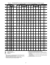
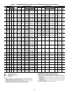
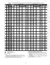
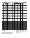
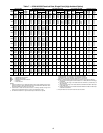
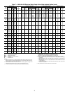
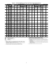
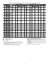
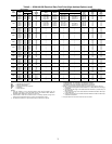
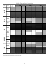
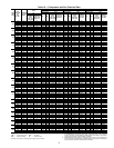
Step 7 — Leak Test Unit — The 30XA units are
shipped with a complete operating charge of R-134a (see
Tables 1A and 1B) and should be under sufficient pressure to
conduct a leak test.
Perform a leak test to ensure that leaks have not developed
during unit shipment. Dehydration of the system is not required
unless the entire refrigerant charge has been lost. There are
several O-ring face seal fittings utilized in the oil line piping. If
a leak is detected at any of these fittings, open the system and
inspect the O-ring surface for foreign matter or damage. Do not
reuse O-rings. Repair any leak found following good refrigera-
tion practice.
Step 8 — Refrigerant Charging
DEHYDRATION — Refer to Carrier Standard Service Tech-
niques Manual, Chapter 1, Refrigerants, Sections 6 and 7 for
details. Do not use compressor to evacuate system.
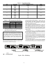
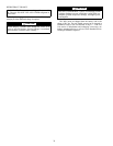
5/8 in. HEX
6" MINIMUM
CLEARANCE FOR
THERMISTOR
REMOVAL
1.188 in.
2.315 in.
1/4-18 NPT
Fig. 39 — Dual Leaving Water Thermistor Well (Part No. 00PPG000008000A) and
Dual Leaving Water Thermistor (Part No. 00PPG000008105A)
a30-3999
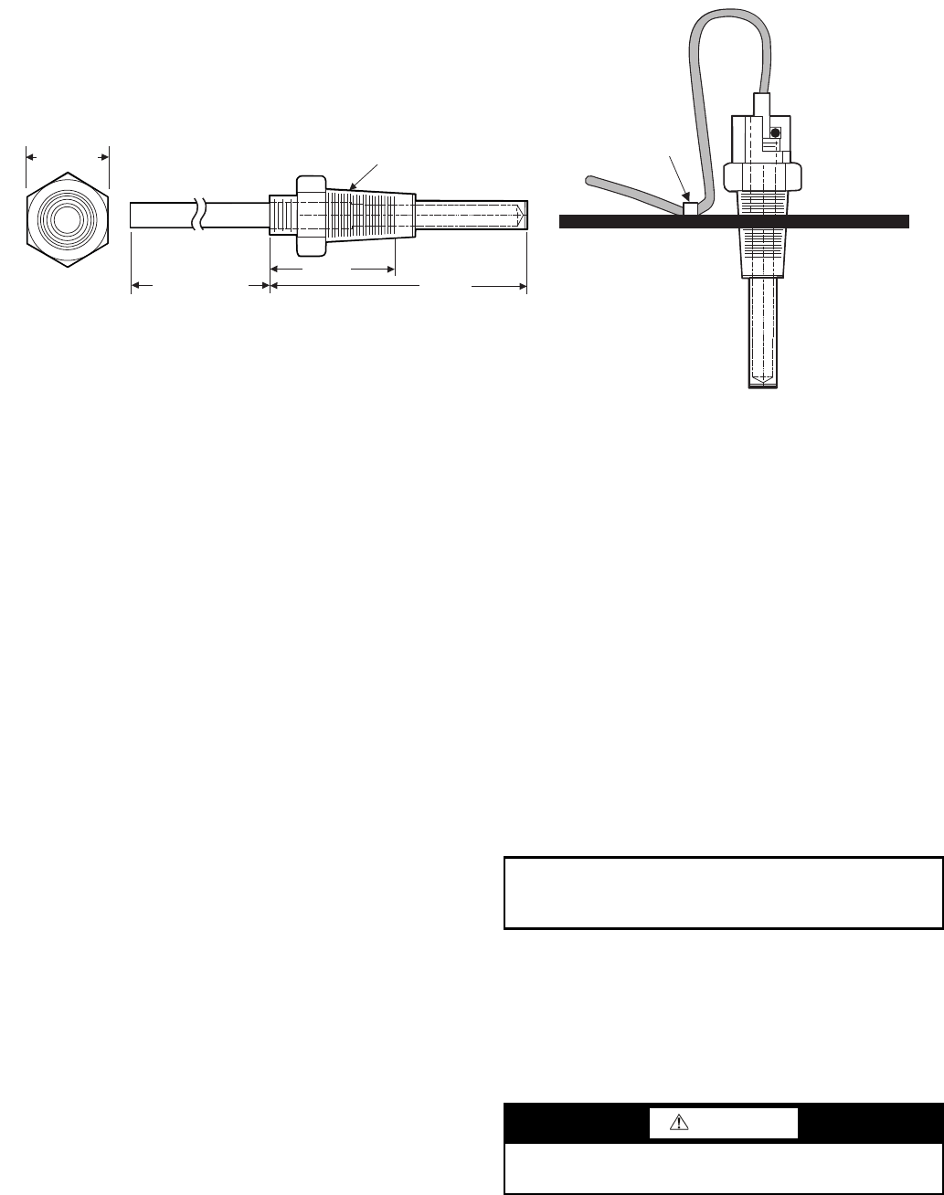
WIRE TIE
LOOP
THERMISTOR WIRE
AND SECURE
TO CHILLED WATER PIPE
INSERT THERMISTOR UNTIL
O-RING MEETS THE
THERMISTOR WELL BODY.
a30-4000
IMPORTANT: These units are designed for use with
R-134a only. DO NOT USE ANY OTHER refriger-
ant in these units.
CAUTION
DO NOT OVERTIGHTEN THESE FITTINGS. Over-
tightening will result in O-ring damage.