53
COOLER PUMP CONTROL — It is required that cooler
pump control be utilized on all chillers unless the chilled water
pump runs continuously or the chilled water system contains a
suitable antifreeze solution. Control of dual external pumps re-
quires installation of the external pump control accessory pack-
age (Part No. 00EFN900003200A).
If cooler pump control is not utilized, it is required that the
chiller be electrically interlocked with the chilled water pump
starter. The interlock should be wired to terminals TB5-1 and
TB5-2. It is also required that the cooler pump output be used
as an override to the chilled water pump control circuit to pro-
vide additional freeze protection.
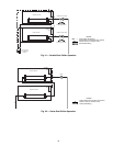
Refer the control and power wiring schematic on page 63
for proper connection of the cooler pump output. The cooler
pump output will remain energized for 30 seconds after all
compressors stop due to an OFF command. In the event a
freeze protection alarm is generated, the cooler pump output
will be energized regardless of the cooler pump control soft-
ware configuration. The cooler pump output is also energized
anytime a compressor is started and when certain alarms are
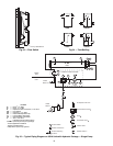
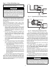
generated. A thermal flow sensor is factory installed in the en-
tering fluid nozzle to prevent operation without flow through
the cooler. See Fig. 29. The flow sensor is factory wired.
Proper software configuration of the cooler pump control
parameters is required to prevent possible cooler freeze-up.
Refer to the Controls, Start-Up, Operation, Service and
Troubleshooting guide for more information.
BRINE UNITS — Special factory modifications to the units
are required to allow them to operate at fluid temperatures
less than 40 F (4.4 C). Be sure that the fluid has sufficient
inhibited glycol or other suitable corrosion-resistant anti-
freeze solution to prevent cooler freeze-up.
PREPARATION FOR YEAR-ROUND OPERATION — In
areas where the piping or unit is exposed to 32 F (0 C) or
lower ambient temperatures, freeze-up protection is required
using inhibited glycol or other suitable corrosion-resistant anti-
freeze solution and electric heater tapes. Heater tapes on piping
should have a rating for area ambient temperatures and be cov-
ered with a suitable thickness of closed-cell insulation. Route
power for the heater tapes from a separately fused disconnect.
Mount the disconnect within sight from the unit per local or
NEC (National Electric Code) codes. Identify disconnect at
heater tape power source with a warning that power must not
be turned off except when servicing unit.
A drain connection is located at the bottom of the cooler
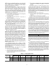
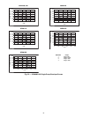
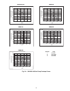
head. See Fig. 2-14 for connection location. Install shut-off
valves to the drain line before filling the system with fluid.
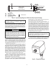
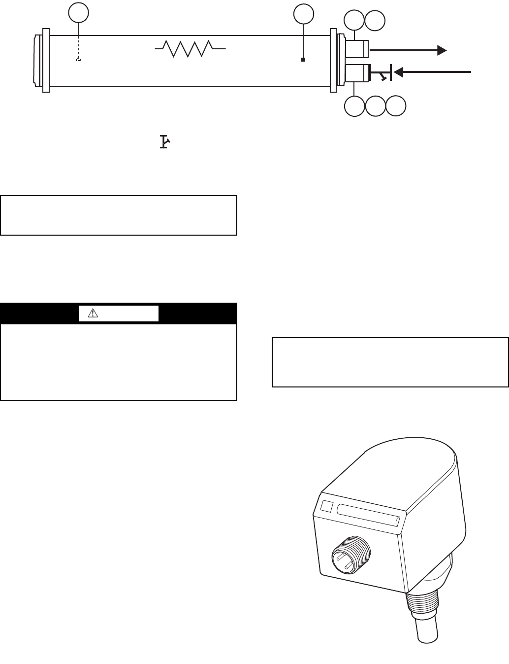
T1
T2
PP
PP
D
V
Heater (Optional)
Chilled Water Out
Chilled Water In
FS
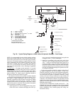
LEGEND
D—Drain,
3
/
4
-in. NPT
FS — Flow Switch
PP — Pipe Plug,
1
/
4
-in. NPT
T1 — Leaving Water Thermistor
T2 — Entering Water Thermistor
V—Vent,
1
/
4
-in. NPT
Fig. 28 — Typical Piping Diagram on 30XA Units without Hydronic Package
a30-4416
20 Mesh Stainer
20 Mesh Strainer
IMPORTANT: Automatic vents should be located in
accessible locations for maintenance purposes and
protected from freezing.
WARNING
Applications that utilize fresh water as the circulated fluid
require that the circulating pump be controlled directly by
the chiller. Operation with fresh water is not fail-safe
should there be a loss of power to the chiller or to the circu-
lating pump. Freeze damage due to power loss or disabling
chiller pump control in fresh water systems will impair or
otherwise negatively affect the warranty.
IMPORTANT: Adding antifreeze solution is the only
certain means of protecting the unit from freeze-up if
heater fails or electrical power is interrupted or lost
while temperatures are below 32 F (0 C).
Fig. 29 — Thermal Flow Sensor
a30-3432


