49
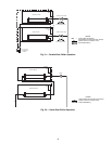
SLAVE CHILLER
CONTROL
BOX
PUMP
MASTER CHILLER
CONTROL
BOX
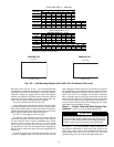
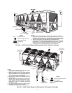
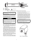
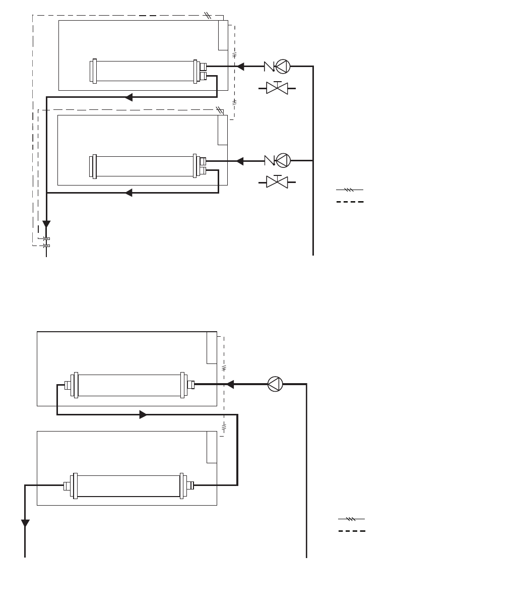
Fig. 22 — Series Dual Chiller Operation
LEGEND
LWT — Leaving Water Temperature
Field-Installed Communication Bus (slashes
indicate number of conductor wires)
Field-Installed Wiring
LEGEND
Field-Installed Communication Bus (slashes
indicate number of conductor wires)
Field-Installed Wiring
Fig. 21 — Parallel Dual Chiller Operation
a30-4417
a30-4418
SLAVE CHILLER
CONTROL
BOX
PUMP & CHECK VALVE
MASTER CHILLER
CONTROL
BOX
DUAL CHILLER
LWT SENSORS
& WELLS
OR ISOLATION VALVE
PUMP & CHECK VALVE
OR ISOLATION VALVE


