


24
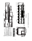
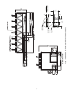
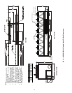
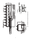
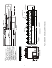
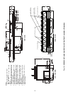
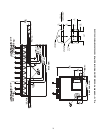
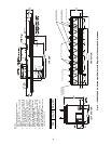
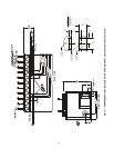
NOTES:
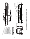
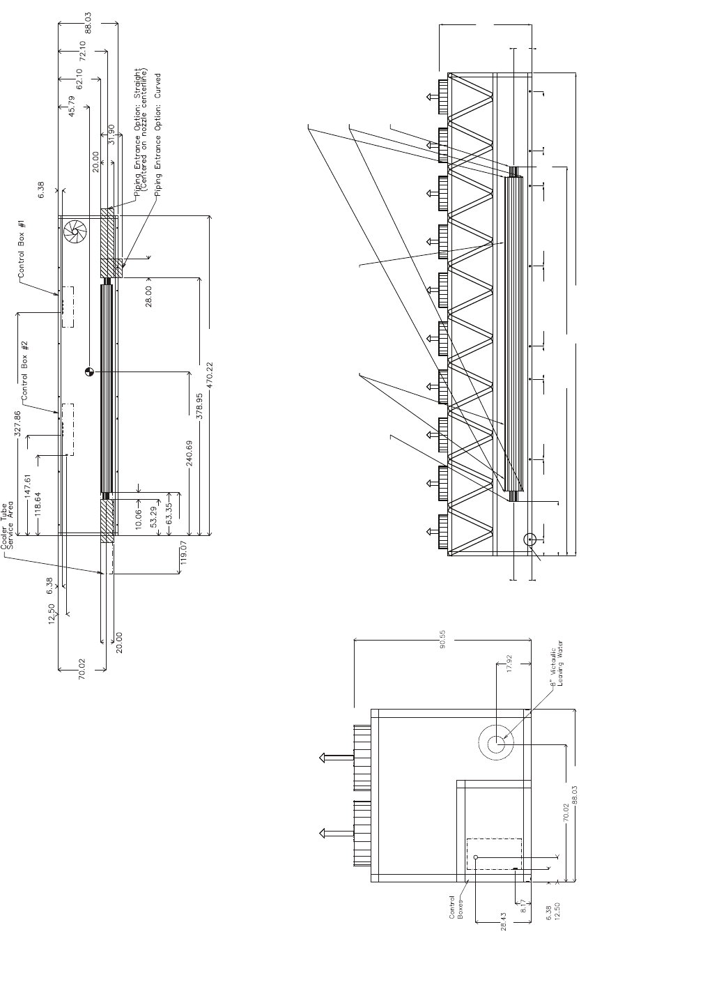
1. Unit must have clearances as follows:
Top — Do not restrict
Sides and Ends — 6 ft (1.8 m) from solid
surface.
2. Temperature relief devices are located on liq-
uid line and economizer assemblies and have
1
/
4
-in. flare connection.
3.
3
/
8
-in. NPT vents and drains located in each
cooler head at each end of cooler.
4. Drawing depicts unit with dual-point power
and standard one-pass cooler. Refer to the
Packaged Chiller Builder program for other
configurations.
5. Actual cooler consists of two separate coolers
piped in series at the factory. Piping may be
split for rigging.
6. Dimensions are shown in inches. Dimensions
in [ ] are in millimeters.
7. Allow 8 ft (2.4 m) on either side of unit for con-
denser coil removal.
a30-4181
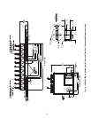
TOP VIEW
LEFT END VIEW
FRONT VIEW
[2300]
[455]
[1779]
[2236]
[162]
[317]
[208]
[722]
3/4 NPT Relief Conn. Female
8" Victaulic Entering Water8" Victaulic Leaving Water
Cooler Vent 3/8 NPT
located in cooler heads
Cooler Drain 3/8 NPT
located in cooler heads
Mounting Holes
Rigging Holes
(See Detail A)
90.55
[2300]
17.92
[455]
17.92
[455]
470.22 [11944]
378.95 [9625]
53.29 [1354]
78.02 [1982]78.02 [1982] 78.02 [1982]78.02 [1982] 58.08 [1475]
33.93
[862]
31.96
[812]
16.1
[409]
[162]
[508]
[810]
[1163]
[1577]
[1831]
[2236]
[711]
[11944]
[9625]
[6114]
[3024]
[508]
[1779]
[317]
[162]
[256]
[1354]
[1609]
[3013]
[3749]
[8328]
Fig. 12 — 30XA400 Air-Cooled Liquid Chiller with Dual Point Connections Dimensions