


10
[2300]
[541]
[269]
[5975]
[1475]
[863]
[3086]
[2769]
[409]
[2410]
[1872]
[162]
[397]
[148]
[2769]
[508]
B
[3086]
[3810]
[5975]
[508]
[885]
[2236]
[1756]
[1502]
A
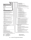
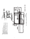
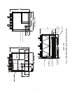
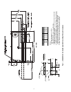
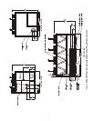
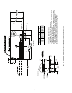
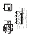
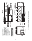
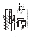
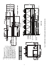
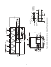
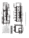
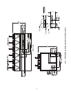
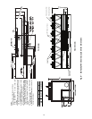
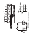
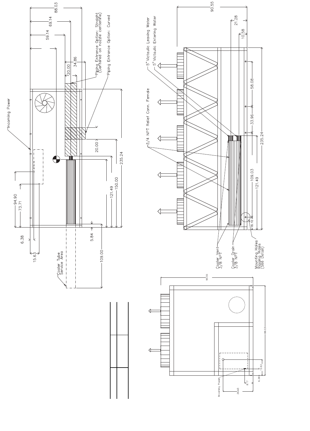
NOTES:
1. Unit must have clearances as follows:
Top — Do not restrict
Sides and Ends — 6 ft (1.8 m) from solid
surface.
2. Temperature relief devices are located on
liquid line and economizer assemblies and
have
1
/
4
-in. flare connection.
3.
3
/
8
-in. NPT vents and drains located in
each cooler head at each end of cooler.
4. Drawing depicts unit with single-point
power, standard two-pass cooler, and
nominal voltage range of 380 to 575 v.
Refer to the Packaged Chiller Builder pro-
gram for other configurations.
5. Dimensions are shown in inches. Dimen-
sions in [ ] are in millimeters.
6. Allow 8 ft (2.4 m) on either side of unit for
condenser coil removal.
30XA UNIT A B
140 44.63 [1134] 115.88 [2943]
160 44.61 [1133] 115.64 [2937]
a30-4404
TOP VIEW
FRONT VIEW
LEFT END VIEW
[2300]
[2236]
[748]
[208]
[162]
[397]
Fig. 5 — 30XA140,160 Air-Cooled Liquid Chiller without Pump Dimensions