


57
NOTE: Do not use automobile anti-freeze, or any other fluid
that is not approved for heat exchanger duty. Only use appro-
priately inhibited glycols, concentrated to provide adequate
protection for the temperature considered.
SYSTEM PRESSURIZATION — A proper initial cold fill
pressure must be established before filling of the unit. The
initial cold fill pressure is the pressure applied at the filling
point to fill a system to its highest point, plus a minimum
pressure at the top of the system (4 psig minimum [27.6 kPa])
to operate air vents and positively pressurize the system. The
expansion tank is very important to system pressurization. The
expansion tank serves several purposes:
1. Provide NPSHR (Net Positive Suction Head Required)
for the pump to operate satisfactorily.
2. Set system pressure.
3. Accommodate expansion/contraction of water due to
temperature changes.
4. Acts as a pressure reference for the pump.
The expansion tank pressure must be set BEFORE the
system is filled. Follow the manufacturer’s recommendation
for instructions on setting the pressure in the expansion tank.
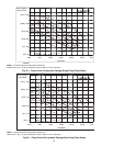
NPSHR information is provided on the Pump Curves in
Fig. 33-36 for units with factory-installed hydronic kits. See
Table 4 for pump impeller sizes.
Once the system is pressurized, the pressure at the connec-
tion point of the expansion tank to water piping will not change
unless the water loop volume changes (either due to addition/
subtraction of water or temperature expansion/contraction).
The pressure at this point remains the same regardless of
whether or not the pump is running.
Since the expansion tank acts as a reference point for the
pump, there cannot be two reference points (two expansion
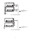
tanks) in a system, unless manifolded together. Where two or
more 30XA chillers with the hydronic option are installed in
parallel, there should not be more than one expansion tank in
the system, unless manifolded together as seen in Fig. 27. It is
permissible to install the expansion tank(s) in a portion of the
return water line that is common to all pumps, providing that
the tank is properly sized for combined system volume.
If the application involves two or more chillers in a primary
secondary system, a common place for mounting the expan-
sion tank is in the chilled water return line, just before the
decoupler. See Fig. 27 for placement of expansion tank in
primary-secondary systems.
If a diaphragm expansion tank is utilized (a flexible
diaphragm physically separates the water/air interface) it is not
recommended to have any air in the water loop. See the section
on air separation on page 51 for instructions on providing air
separation equipment.
FILLING THE SYSTEM — The initial fill of the chilled
water system must accomplish three goals:
1. The entire piping system must be filled with water.
2. The pressure at the top of the system must be high enough
to vent air from the system (usually 4 psig [27.6 kPa] is
adequate for most vents).
3. The pressure at all points in the system must be high
enough to prevent flashing in the piping or cavitation in
the pump.
The pressure created by an operating pump affects system
pressure at all points except one — the connection of the
expansion tank to the system. This is the only location in the
system where pump operation will not give erroneous pressure
indications during the fill. Therefore, the best location to install
the fill connection is close to the expansion tank. An air vent
should be installed close by to help eliminate air that enters
during the fill procedure.
When filling the system, ensure the following:
1. Remove temporary bypass piping and cleaning/flushing
equipment.
2. Check to make sure all drain plugs are installed.
Normally, a closed system needs to be filled only once. The
actual filling process is a fairly simple procedure. All air should
be purged or vented from the system. Thorough venting at high
points and circulation at room temperature for several hours is
highly recommended.
NOTE: Local codes concerning backflow devices and other
protection of the city water system should be consulted and
followed to prevent contamination of the public water supply.
This is critical when antifreeze is used in the system.
SET WATER FLOW RATE — Once the system is cleaned,
pressurized, and filled, the flow rate through the chiller needs
to be established. On units with the hydronic package, this can
be accomplished by using the balancing valve. Follow the
manufacturer’s recommendations for setting the balancing
valve. Local codes may prohibit restricting the amount of water
using the balancing valve for a given motor horsepower. In this
case, use the method listed in the Pump Modification/
Trimming section. See below for the type of combination valve
in 30XA units with the optional hydronic package.
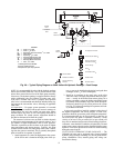
NOTE: Carrier recommends a differential pressure gage when
measuring pressures across the pumps or balancing valves.
This provides for greater accuracy and reduces error build-up
that often occurs when subtracting pressures made by different
gages.
A rough estimate of water flow can also be obtained from
the pressure gages across the 30XA heat exchanger.
Figure 33 and 34 shows the relationship between gpm and
heat exchanger pressure drop. It should be noted that these
curves are for fresh water and “clean” heat exchangers; they do
not apply to heat exchangers with fouling. To read the chart,
subtract the readings of the two pressure gages on the hydronic
kit. This number is the pressure drop across the heat exchanger.
Adjust the factory-installed balancing valve or external balanc-
ing valve (in units without hydronic package) until the correct
pressure drop is obtained for the required flow.
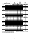
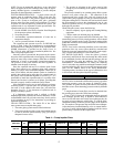
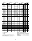
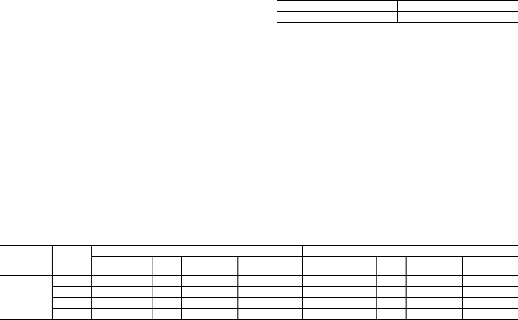
Table 4 — Pump Impeller Sizes
*Option Code refers to the Hydronics Option (position 11) in the model number. See Fig. 1 for option identification.
30XA UNIT SIZE SINGLE/DUAL PUMP
090-160 FTV-5 in.
30XA
UNIT SIZE
PUMP
Hp
SINGLE PUMP DUAL PUMP
Option Code* Rpm
Impeller Dia.
(in.)
Pump Curve Option Code* Rpm
Impeller Dia.
(in.)
Pump Curve
090-160
5 1 3450 4.5 I 7 3450 4.5 II
7.5 2 3450 5 I 8 3450 5 II
10 3 3450 5.4 I B 3450 5.4 II
15 4 3450 6.1 I C 3450 6.1 II