


28
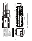
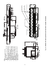
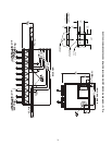
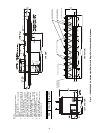
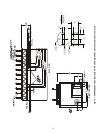
NOTES:
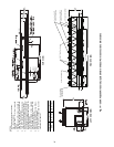
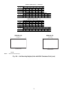
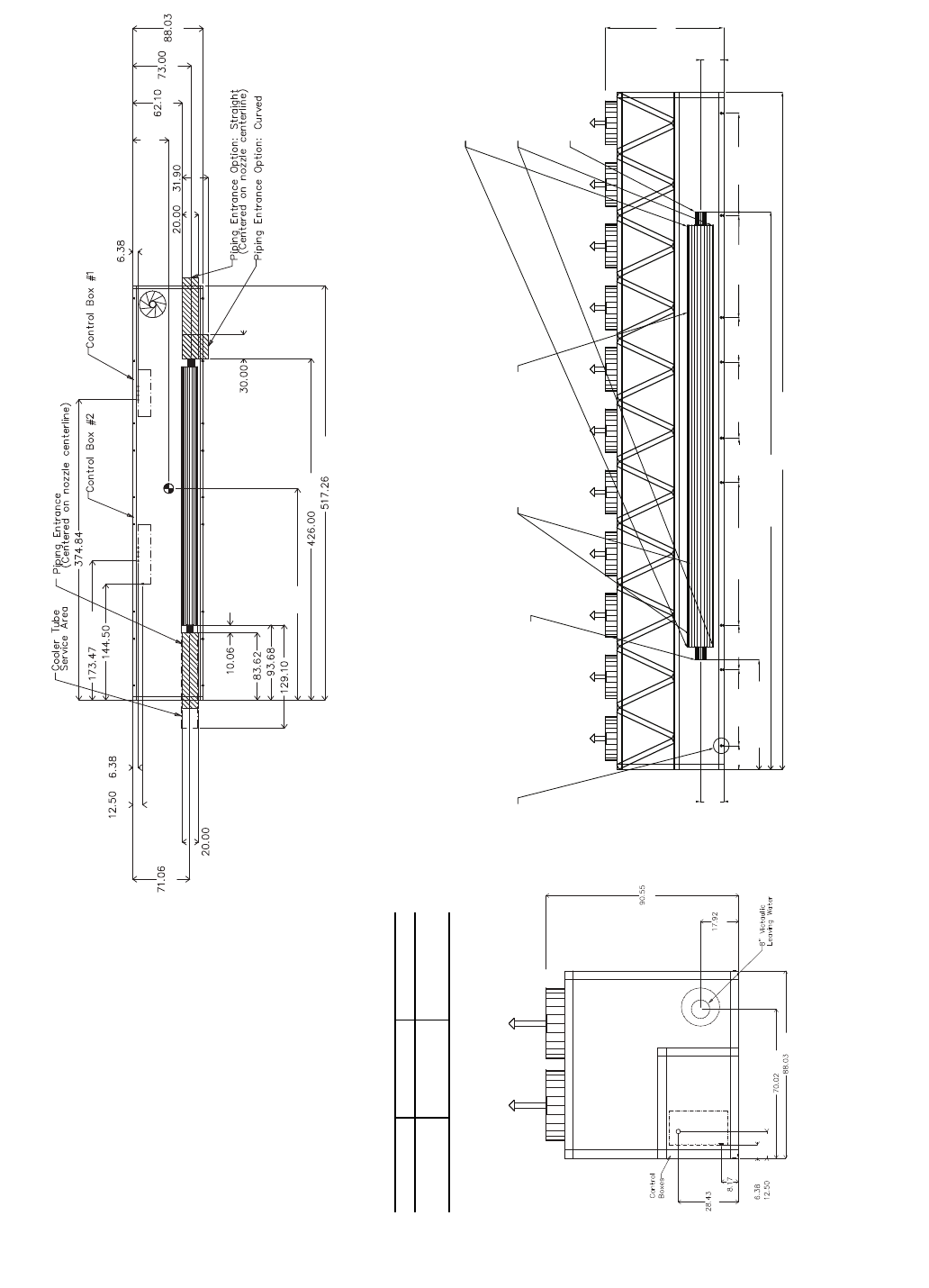
1. Unit must have clearances as follows:
Top — Do not restrict
Sides and Ends — 6 ft (1.8 m) from solid
surface.
2. Temperature relief devices are located on
liquid line and economizer assemblies and
have
1
/
4
-in. flare connection.
3.
3
/
8
-in. NPT vents and drains located in
each cooler head at each end of cooler.
4. Drawing depicts unit with dual-point power
and standard one-pass cooler. Refer to
the Packaged Chiller Builder program for
other configurations.
5. Actual cooler consists of two separate
coolers piped in series at the factory. Pip-
ing may be split for rigging.
6. Dimensions are shown in inches. Dimen-
sions in [ ] are in millimeters.
7. Allow 8 ft (2.4 m) on either side of unit for
condenser coil removal.
30XA UNIT A B
450 44.71 [1136] 264.7 [6723]
500 44.78 [1137] 263.99 [6705]
a30-4183
3/4 NPT Relief Conn. Female
8" Victaulic Entering Water
8" Victaulic Leaving Water
Cooler Vent 3/8 NPT
located in cooler heads
Cooler Drain 3/8 NPT
located in cooler heads
Mounting Holes
Rigging Holes
(See Detail A)
90.55
[2300]
17.92
[455]
17.92
[455]
517.26 [13138]
426.0 [10820]
83.62 [2124]
109.03
[2769]
78.02
[1982]
78.02
[1982]
58.08
[1475]
58.08
[1475]
33.97
[863]
33.97
[863]
33.96
[863]
18.07
[459]
TOP VIEW
FRONT VIEWLEFT END VIEW
[2300]
[455]
[1779]
[2236]
[162]
[317]
[208]
[722]
[162]
[508]
[810]
A
[1577]
[1854]
[2236]
[762]
[13138]
[10820]
B
[256]
[2124]
[2379]
[3279]
[508]
[1805]
[317]
[162]
[9521]
[3670]
[4406]
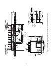
Fig. 14 — 30XA450,500 Air-Cooled Liquid Chiller with Dual Point Connections Dimensions