


3
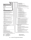
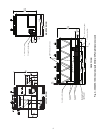
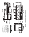
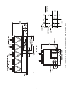
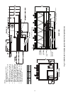
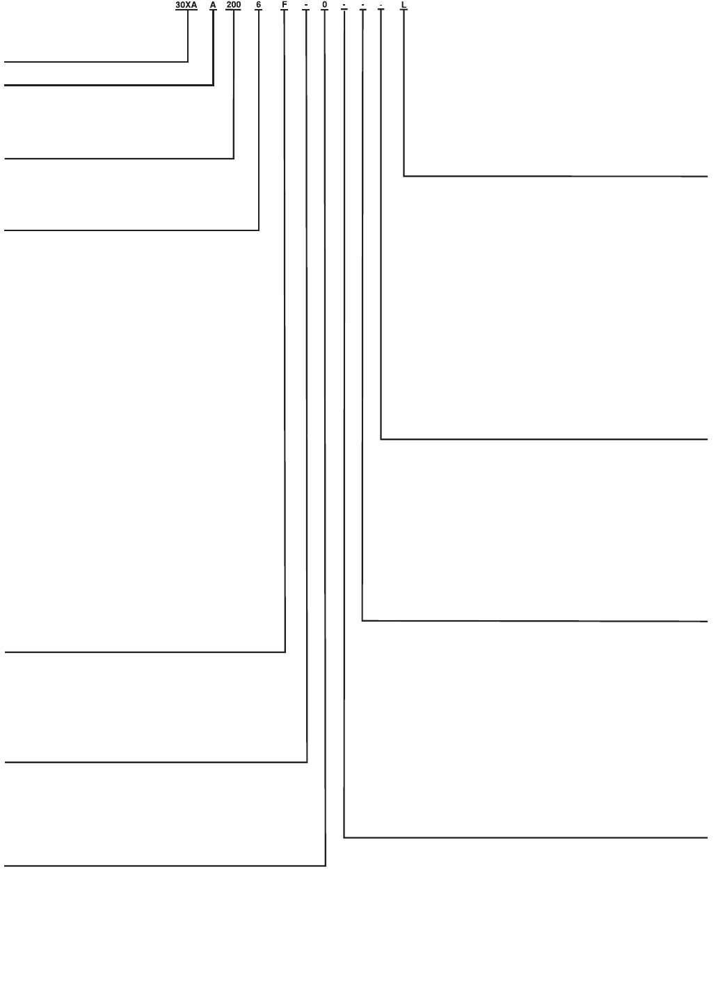
Fig. 1 — AquaForce
®
Chiller Model Number Designation
a30-4401
LEGEND
CFSP — Coil Face Shipping Protection
EMM — Energy Management Module
LON — Local Operating Network
MCHX — Microchannel Heat Exchanger
XL — Across-the-Line Starter
30XA – AquaForce® Air-Cooled Chiller
Design Series
Unit Sizes
080 140 240 350
090 160 260 400
100 180 280 450
110 200 300 500
120 220 325
Voltage
1 – 575-3-60
2 – 380-3-60
4 – 230-3-60
6 – 460-3-60
7 – 200-3-60
Condenser Coil/Ambient/Low Sound Options
- – Aluminum Fin/Copper Tube, High Ambient Temperature
0 – Copper Fin/Copper Tube, High Ambient Temperature
1 – Aluminum Pre-Coat Fin/Copper Tube, High Ambient Temperature
2 – Aluminum E-Co
at Fin/Copper Tube, High Ambient Temperature
3 – Copper E-Coat Fin/Copper Tube, High Ambient Temperature
4 – Novation® Heat Exchanger (MCHX), High Ambient
Temperature
5 – MCHX E-Coat, High Ambient Temperature
6 – Aluminum Fin/Copper Tube, High Ambient Temperature,
Low Sound
7 – Copper Fin/Copper Tube, High Ambient Temperature, Low Sound
8 – Aluminum Pre-Coat Fin/Copper Tube, High Ambient Temperature,
Low Sound
9 – Aluminum E-Coat Fin/Copper Tube, High Ambient Temperature,
Low Sound
B – Copper E-Coat Fin/Copper Tube, High Ambient Temperature,
Low Sound
C – MCHX, High Ambient Temperature, Low Sound
D – MCHX E-Coat, High Ambient Temperature, Low Sound
F – Aluminum Fin/Copper Tube, Standard Ambient Temperature,
Low Sound
G – Copper Fin/Copper Tube, Standard Ambient Temperature,
Low Sound
H – Aluminum Pre-Coat Fin/Copper Tube, Standard Ambient
Temper
ature, Low Sound
J – Aluminum E-Coated Fin/Copper Tube, Standard Ambient
Temperature, Low Sound
K – Copper E-Coat Fin/Copper Tube, Standard Ambient Temperature,
Low Sound
L – MCHX, Standard Ambient Temperature, Low Sound
M – MCHX E-Coat, Standard Ambient Temperature, Low Sound
N – Aluminum Fin/Copper Tube, Standa
rd Ambient Temperature
P – Copper Fin/Copper Tube, Standard Ambient Temperature
Q – Aluminum Pre-Coat Fin/Copper Tube, Standard Ambient
Temperature
R – Aluminum E-Coat Fin/Copper Tube, Standard Ambient
Temperature
S – Copper E-Coat Fin/Copper Tube, Standard Ambient Temperature
T – MCHX, Standard Ambient Temperature
V – MCHX E-Coat, Standard Ambient Temperat
ure
Cooler/Brine Options
0 – Integral Cooler with Heater
3 – Integral Cooler with Heater, Minus One Pass
5 – Integral Cooler with Heater, Plus One Pass
7 – Integral Cooler with Heater, Full End Screen
H – Integral Cooler with Heater, Plus One Pass, Brine
K – Integral Cooler with Heater, Minus One Pass, Full End Screen
M – Integral Cooler with Heater, Plus One Pass, Full End Screen
V – Integral Cooler with Heater, Plus One Pass, Brine, Full End Screen
Packaging/Security Options
0 – Coil Fa
ce Shipping Protection (CFSP), Skid
1 – CFSP, Skid, Top Crate, Bag
3 – CFSP, Coil Trim Panels
4 – CFSP, Skid, Coil Trim Panels
5 – CFSP, Skid, Top Crate, Bag, Coil Trim Panels
7 – CFSP, Coil Trim Panels, Upper and Lower Grilles
8 – CFSP, Skid, Coil Trim Panels, Upper and Lower Grilles
9 – CFSP, Skid, Top Crate, Bag, Coil Trim Panels, Upper and Lower Grilles
C – CFSP, Trim Panels, Upper and Lower Grilles, Upper Hail G
uards
D – CFSP, Skid, Coil Trim Panels, Upper and Lower Grilles, Upper Hail Guards
F – CFSP, Skid, Top Crate, Bag, Trim Panels, Upper and Lower Grilles,
Upper Hail Guards
L – CFSP
Controls/Communication Options
- – Navigator™ Display
0 – Navigator Display, EMM
1 – Navigator Display, Service Option
2 – Navigator Display, EMM, Service Option
3 – Tou
ch Pilot™ Display
4 – Touch Pilot Display, EMM
5 – Touch Pilot Display, Service Option
6 – Touch Pilot Display, EMM, Service Option
7 – Navigator Display, BACnet Translator
8 – Navigator Display, BACnet Translator, EMM
9 – Navigator Display, BACnet Translator, Service Option
B – Navigator Display, BACnet Translator, EMM, Service Option
C – Touch Pilot Display, BACnet Translator
D – Touch Pilot Display, BACnet Translator, EMM
F – Touch Pilot Display, BACnet Translator, Service Option
G – Touch Pilot Display, BACnet Translator, EMM, Service Option
H – Navigator Display, LON Translator
J – Navigator Display, LON Translator, EMM
K – Navigator Displa
y, LON Translator, Service Option
L – Navigator Display, LON Translator, EMM, Service Option
M – Touch Pilot Display, LON Translator
N – Touch Pilot Display, LON Translator, EMM
P – Touch Pilot Display, LON Translator, Service Option
Q – Touch Pilot Display, LON Translator, EMM, Service Option
Electrical Options
- – Single Point Power, XL, Terminal Block, No Control Transformer
0 –
Single Point Power, Wye-Delta, Terminal Block, No Control Transformer
3 – Dual Point Power, XL, Terminal Block, No Control Transformer
4 – Dual Point Power, Wye-Delta, Terminal Block, No Control Transformer
7 – Single Point Power, XL, Disconnect, No Control Transformer
8 – Single Point Power, Wye-Delta, Disconnect, No Control Transformer
C – Dual Point Power, XL, Disconnect, No Control Transformer
D – Dual Point Power, Wye-Delta, Disconnect, No Control Transformer
H – Single Point Power, XL, Terminal Block, Control Transformer
J – Single Point Power, Wye-Delta, Terminal Block, Control Transformer
M – Dua
l Point Power, XL, Terminal Block, Control Transformer
N – Dual Point Power, Wye-Delta, Terminal Block, Control Transformer
R – Single Point Power, XL, Disconnect, Control Transformer
S – Single Point Power, Wye-Delta, Disconnect, Control Transformer
W – Dual Point Power, XL, Disconnect, Control Transformer
X – Dual Point Power, Wye-Delta, Disconnect, Control Transformer
Refrigeration Circuit Options
- – None
0 – Suction Line Insulation
1 – Suction Service Valves
2 – Low Ambient Temperature Head Pressure Control
3 – Su
ction Line Insulation, Suction Service Valves
4 – Suction Line Insulation, Low Ambient Temperature Head Pressure Control
5 – Suction Service Valves, Low Ambient Temperature Head Pressure Control
6 – Suction Line Insulation, Suction Service Valves, Low Ambient Temperature
Head Pressure Control
7 – Minimum Load Control
8 – Suction Line Insulation, Minimum Load Control
9 – Suction Service Valves, Minimu
m Load Control
B – Low Ambient Temperature Head Pressure Control, Minimum Load Control
C – Suction Line Insulation, Suction Service Valves, Minimum Load Control
D – Suction Line Insulation, Low Ambient Temperature Head Pressure
Control, Minimum Load Control
F – Suction Service Valves, Low Ambient Temperature Head Pressure
Control, Minimum Load Control
G – Suction Line Insulation, Suction Service Valves, Low Ambient Temperature
Head Pressure Control, Minimum Load Control
Hydronic Pump Package Options
- – None
1 – Single Pump, 5 HP
2 – Single Pump, 7.5 HP
3 – Single Pump, 10 HP
4 – Single Pump, 15 HP
7 – Dual Pump, 5 HP
8 – Dual Pump, 7.5 HP
B – Dual Pump, 10 HP
C – Dual Pump, 15 HP
Quality Assurance
Certified to ISO 9001:2000