


Manufacturer reserves the right to discontinue, or change at any time, specifications or designs without notice and without incurring obligations.
Catalog No. 04-53300026-01 Printed in U.S.A. Form 30XA-10SI Pg 1 11-09 Replaces: 30XA-5SI
Installation Instructions
CONTENTS
Page
SAFETY CONSIDERATIONS. . . . . . . . . . . . . . . . . . . . . . 1
INTRODUCTION . . . . . . . . . . . . . . . . . . . . . . . . . . . . . . . . . . 1
INSTALLATION . . . . . . . . . . . . . . . . . . . . . . . . . . . . . . . . 1-78
Storage . . . . . . . . . . . . . . . . . . . . . . . . . . . . . . . . . . . . . . . . . . 1
Step 1 — Inspect Shipment . . . . . . . . . . . . . . . . . . . . . . 1
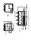
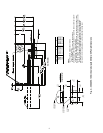
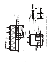
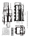
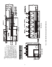
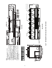
Step 2 — Place, Mount and Rig Unit. . . . . . . . . . . . . 2
•PLACING UNIT
• MOUNTING UNIT
• RIGGING UNIT
Step 3 — Cooler Fluid and Drain Piping
Connections . . . . . . . . . . . . . . . . . . . . . . . . . . . . . . . . . . 41
• GENERAL
• UNITS WITH A HYDRONIC PUMP PACKAGE
• UNITS WITHOUT A HYDRONIC PUMP PACKAGE
• DUAL CHILLER CONTROL
• COOLER PUMP CONTROL
• BRINE UNITS
• PREPARATION FOR YEAR-ROUND OPERATION
Step 4 — Fill the Chilled Water Loop . . . . . . . . . . . . 56
• WATER SYSTEM CLEANING
• WATER TREATMENT
• SYSTEM PRESSURIZATION
• FILLING THE SYSTEM
• SET WATER FLOW RATE
• PUMP MODIFICATION/TRIMMING
• FREEZE PROTECTION
• PREPARATION FOR WINTER SHUTDOWN
Step 5 — Make Electrical Connections . . . . . . . . . . 62
• POWER SUPPLY
• FIELD POWER CONNECTIONS
•POWER WIRING
• FIELD CONTROL POWER CONNECTIONS
• CARRIER COMFORT NETWORK®
COMMUNICATION BUS WIRING
• NON-CCN COMMUNICATION WIRING
• FIELD CONTROL OPTION WIRING
• DUAL CHILLER LEAVING WATER SENSOR
Step 6 — Install Accessories . . . . . . . . . . . . . . . . . . . . 77
• ENERGY MANAGEMENT MODULE
• REMOTE ENHANCED DISPLAY
• LOW AMBIENT TEMPERATURE OPERATION
• MINIMUM LOAD ACCESSORY
• UNIT SECURITY/PROTECTION ACCESSORIES
• COMMUNICATION ACCESSORIES
• SERVICE OPTIONS
• CONTROL TRANSFORMER
Step 7 — Leak Test Unit . . . . . . . . . . . . . . . . . . . . . . . . . 77
Step 8 — Refrigerant Charging. . . . . . . . . . . . . . . . . . 77
• DEHYDRATION
• REFRIGERANT CHARGE
SAFETY CONSIDERATIONS
Installing, starting up, and servicing this equipment can be
hazardous due to system pressures, electrical components, and
equipment location. Only trained, qualified installers and service
mechanics should install, start up, and service this equipment.
When working on the equipment, observe precautions in the
literature, and on tags, stickers, and labels attached to the
equipment.
• Follow all safety codes.
• Wear safety glasses and work gloves.
• Use care in handling, rigging, and setting bulky equipment.
INTRODUCTION
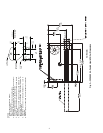
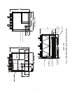
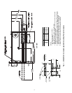
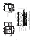
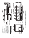
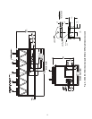
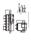
These instructions cover installation of 30XA080-500 air-
cooled liquid chillers with electronic controls and units with
factory-installed options (FIOPs). See Fig. 1.
INSTALLATION
Storage —
If the unit is to be stored for a period of time be-
fore installation or start-up, be sure to protect the machine
from construction dirt. Keep protective shipping covers in
place until the machine is ready for installation.
Step 1 — Inspect Shipment — Inspect unit for dam-
age upon arrival. If damage is found, immediately file a claim
with the shipping company, and contact your local Carrier
representative.
WARNING
Electrical shock can cause personal injury and death. Shut
off all power to this equipment during installation. There
may be more than one disconnect switch. Tag all discon-
nect locations to alert others not to restore power until work
is completed.
IMPORTANT: This equipment generates, uses, and
can radiate radio frequency energy and if not installed
and used in accordance with these instructions may
cause radio interference. It has been tested and found
to comply with the limits of a Class A computing
device as defined by FCC (Federal Communications
Commission, U.S.A.) regulations, Subpart J of Part 15,
which are designed to provide reasonable protection
against such interference when operated in a commer-
cial environment.
AQUAFORCE
®
30XA080-500
Air-Cooled Liquid Chillers