


74
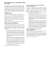
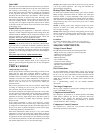
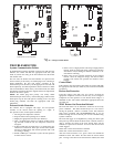
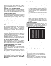
UTILITY RELAY
*
UTILITY SIGNAL
OPEN RELAY
* SUPPLIED BY UTILITY PROVIDER
MODEL
PLUG
A06525
LLS
Liquid Line Solenoid
MODEL
PLUG
A06526
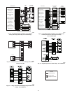
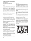
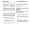
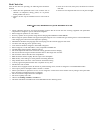
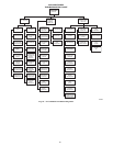
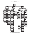
Fig. 54 – 2--Stage Control Board
TROUBLESHOOTING
Systems Communication Failure
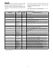
If communication with the Evolution control is lost with the User
Interface, the control will flash the appropriate fault code. (See
Table 23.) Check the wiring to the User Interface and the indoor
and outdoor units.
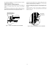
On new units, the model and serial numbers are input into the
board’s memory at the factory. If a model plug is lost or missing at
initial installation, the unit will operate according to the
information input at the factory and the appropriate error code will
flash temporarily. An RCD replacement board contains no model
and serial information. If the factory control board fails, the model
plug must be transferred from the original board to the replacement
board for the unit to operate.
NOTE: The model plug takes priority over factory model
information input at the factory. If the model plug is removed after
initial power up, the unit will operate according to the last valid
model plug installed, and flash the appropriate fault code
temporarily.
Pressure Switch Protection
The outdoor unit is equipped with high-- and low--pressure
switches. If the control senses the opening of a high-- or
low--pressure switch, it will respond as follows:
1. De--energize the compressor contactor.
2. Keep the outdoor fan operating for 15 minutes.
3. Display the appropriate fault code (see Table 23).
4. After a 15 minute delay, if there is a call for cooling or heat-
ing and LPS or HPS is reset, the compressor contactor is
energized.
5. If LPS or HPS has not closed after a 15 minute delay, the
outdoor fan is turned off. If the open switch closes anytime
after the 15 minute delay, then resume operation with a call
for cooling or heating.
6. If LPS or HPS trips 3 consecutive cycles, the unit operation
is locked out for 4 hours.
7. In the event of a high--pressure switch trip or high--pressure
lockout, check the refrigerant charge, outdoor fan operation,
and outdoor coil (in cooling) for airflow restrictions, or in-
door airflow in heating.
8. In the event of a low--pressure switch trip or low--pressure
lockout, check the refrigerant charge and indoor airflow
(cooling) and outdoor fan operation and outdoor coil in
heating.
Control Fault
If the outdoor unit control board has failed, the control will flash
the appropriate fault code (see Table 23). The control board should
be replaced.
Brown--Out Protection
If the line voltage is less than 187v for at least 4 seconds, the
appropriate compressor contactor and fan relay are de--energized.
Compressor and fan operation are not allowed until voltage is a
minimum of 190v. The control will flash the appropriate fault code
(see Table 23).
2230V Brown--Out Protection Defeated
The brownout feature can be defeated if needed for severe noisy
power conditions. This defeat should always be a last resort to
solving the problem. Defeat is available on the User Interface
setup screen (available with SYSTXBBUID01--B), or can be
initiated through the forced defrost pins for non--communicating
systems as follows:
The brownout toggle is accomplished by sorting the defrost pins
from power up with the OAT and OCT sensor connector removed.
After 3 seconds, the status of the force defrost short and the
OAT/OCT as open will be checked. If correct, then the brownout
will be toggled.
Status code 6 shows the brownout is disabled.
Status code 5 shows the brownout is active.
After the brownout defeat is set, power down and reinstall the
OAT/OCT sensor and remove the short from the forced defrost
pins. As long as the short on the forced defrost remains, the OAT