


62
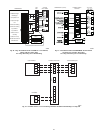
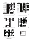
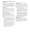
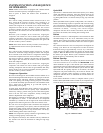
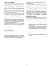
UTILITY RELAY *
UTILITY SIGNAL
OPEN RELAY
* SUPPLIED BY UTILITY PROVIDER
MODEL
PLUG
LLS
Liquid Line Solenoid
MODEL
PLUG
A06525/.A06526
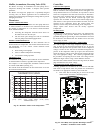
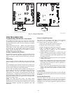
Fig. 45 – 2--Stage Control Board
TROUBLESHOOTING
Troubleshooting (HK38EA015) circuit board
The Evolution Series outdoor units all use the same control board.
A model plug is used to identify the system type, and set the
operating parameters for airflow, start circuit timing etc. (see Model
Plug section)
Replacement boards may have a different part number from the
original board. A newer board will always be backward compatible
to previous units if it is superseded at RCD. Old boards are not
always forward compatible due to new functions, or software
changes made to resolve field issues.
Systems Communication Failure
If communication with the Evolution control is lost with the User
Interface, the control will flash the appropriate fault code. (See
Table 21.) Check the wiring to the UI and the indoor and outdoor
units.
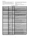
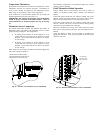
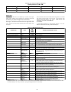
Model Plug
Each control board contains a model plug. The correct model plug
must be installed for or the system to operate properly. (See Table
18.)
The model plug is used to identify the type and size of unit to the
control. On 286B models, the model plug is also used to determine
the start sequence timing for each individual model.
On new units, the model and serial numbers are input into the
board’s memory at the factory. If a model plug is lost or missing at
initial installation, the unit will operate according to the
information input at the factory and the appropriate error code will
flash temporarily. An RCD replacement board contains no model
and serial information. If the factory control board fails, the model
plug must be transferred from the original board to the replacement
board for the unit to operate.
NOTE: The model plug takes priority over factory model
information input at the factory. If the model plug is removed after
initial power up, the unit will operate according to the last valid
model plug installed, and flash the appropriate fault code
temporarily.
Pressure Switch Protection
The outdoor unit is equipped with high-- and low--pressure
switches. If the control senses the opening of a high-- or
low--pressure switch, it will respond as follows:
1. De--energize the appropriate compressor contactor.
2. Keep the outdoor fan operating for 15 minutes.
3. Display the appropriate fault code (see Table 21).
4. After a 15 minute delay, if there is a call for cooling or
heating and LPS or HPS is reset, the appropriate
compressor contactor is energized.
5. If LPS or HPS has not closed after a 15 minute delay, the
outdoor fan is turned off. If the open switch closes anytime
after the 15 minute delay, then resume operation with a call
for cooling or heating.
6. If LPS or HPS trips 3 consecutive cycles, the unit operation
is locked out for 4 hours.
7. In the event of a high--pressure switch trip or high--pressure
lockout, check the refrigerant charge, outdoor fan operation,
and outdoor coil (in cooling) for airflow restrictions, or
indoor airflow in heating.
8. In the event of a low--pressure switch trip or low--pressure
lockout, check the refrigerant charge and indoor airflow
(cooling) and outdoor fan operation and outdoor coil in
heating.
Control Fault
If the outdoor unit control board has failed, the control will flash
the appropriate fault code (see Table 21). The control board should
be replaced.
Brown--Out Protection
If the line voltage is less than 187v for at least 4 seconds, the
appropriate compressor contactor and fan relay are de--energized.
Compressor and fan operation are not allowed until voltage is a
minimum of 190v. The control will flash the appropriate fault code
(see Table 21).