


72
Quiet Shift
Quiet Shift is a field--selectable defrost mode which may eliminate
occasional noise that could be heard at the start of the defrost cycle
and restarting of the heating cycle. On a non--communicating
system, this feature must be enabled by selecting the 3rd position
of the 3--position dip switch. For communicating (Evolution)
systems, it must be enabled at the User Interface. When activated,
the following sequence of operation will occur. Reversing valve
will energize and compressor will turn off for 30 seconds, then turn
back on to complete defrost. At the end of the defrost cycle, the
reversing valve de--energizes, compressor will turn off for another
30 seconds, and the fan will turn off for 40 seconds, before starting
in the heating mode.
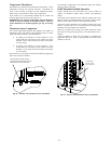
Liquid--Line Solenoid Accessory
In heat pump long--line applications, a liquid--line solenoid is
required to control refrigerant migration in the heating mode. The
solenoid should be installed near the outdoor unit with the arrow
facing the outdoor unit. This is the direction of flow control. See
application manual for long--line application details.
Accessory Liquid Solenoid with Evolution
Communicating
Control:
When using the Evolution Control, the liquid--line solenoid output
is provided at the Y1 connection. Connect the solenoid as shown in
the wiring label diagram. This is a 24vac output that is energized
whenever the compressor is energized. It closes, in the compressor
off mode, to prevent refrigerant migration into the unit through the
liquid--line.
On Systems with Accessory Liquid Solenoid Using
a
Non--Communicating
Thermostat:
The liquid solenoid is connect to the Y1 and C terminal
connections. The liquid solenoid closes, in the compressor off
mode, to prevent refrigerant migration into the unit through the
liquid--line.
CHECK CHARGE
Charged in high or low stage
Factory charge amount and desired subcooling are shown on unit
rating plate for high stage. Charging method is shown on
information plate inside unit. To properly check or adjust charge,
conditions must be favorable for subcooling charging. Favorable
conditions exist when the outdoor temperature is between 70_F
and 100_F (21.11_C and 37.78_C), and the indoor temperature is
between 70_F and 80_F (21.11_C and 26.67_C). Follow the
procedure below:
Unit is factory charged for 15ft (4.57 m) of lineset. Adjust charge
by adding or removing 0.6 oz/ft (17.74 g/m) of 3/8 liquid line
above or below 15ft (4.57 m) respectively.
For standard refrigerant line lengths (80 ft/24.38 m or less), allow
system to operatein cooling mode at least 15 minutes. If conditions
are favorable, check system charge by subcooling method. If any
adjustment is necessary, adjust charge slowly and allow system to
operate for 15 minutes to stabilize before declaring a properly
charged system.
If the indoor temperature is above 80_F (26.67_C), and the
outdoor temperature is in the favorable range, adjust system charge
by weight based on line length and allow the indoor temperature to
drop to 80_F (26.67_C) before attempting to check system charge
by subcooling method as described above.
If the indoor temperature is below 70_F (21.11_C), or the outdoor
temperature is not in the favorable range, adjust charge for line set
length above orbelow 15ft (4.57 m) only. Charge level should then
be appropriate for the system to achieve rated capacity. The charge
level could then be checked at another time when the both indoor
and outdoor temperatures are in a more favorable range.
NOTE: If line length is beyond 80 ft (24.38 m) or greater than 20
ft (6.10 m) vertical separation, See Long Line Guideline for
special charging requirements.
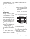
Heating Check Chart Procedure
To check system operation during heating cycle, refer to the Heat
Pump Charging Instructions label on outdoor unit. This chart
indicates whether a correct relationship exists between system
operating pressure and air temperature entering indoor and outdoor
units. If pressure and temperature do not match on chart, system
refrigerant charge may not be correct. Do not use chart to adjust
refrigerant charge.
NOTE: In heating mode, check refrigerant charge only when
pressures are stable. If in doubt, remove charge and weigh in
correct refrigerant charge.
NOTE: When charging is necessary during heating season, charge
must be weighed in accordance with unit rating plate, ±0.6 oz./ft
(±17.74 g/m). of 3/8--in. liquid--line above or below 15 ft (4.57
m)., respectively.
EXAMPLE:
To calculate additional charge required for a 25--ft. line set:
25 ft. -- 15 ft. = 10 ft. X 0.6 oz./ft. = 6 oz. of additional charge.
MAJOR COMPONENTS
2--Stage Control Board
The HP control board controls the following functions:
S High and low stage compressor contactor operation
S Outdoor fan motor operation
S Reversing valve operation
S Defrost operation
S Low ambient cooling
S Crankcase heater operation
S Compressor external protection
S Pressure switch monitoring
S Time Delays
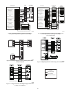
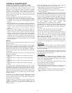
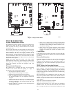
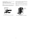
Field Connections
On non--communicating (non--Evolution) system, the two--stage
control receives 24vac low--voltage control system inputs through
the R, C, Y1, Y2 and O connections located at the bottom of the
control board (see Fig. 54.) On a non--communicating system,
output W1 is connected at the bottom of the control board for
auxiliary heat.
For a communicating system, use the ABCD Evolution
connections.
Two Stage Compressor
The two stage compressor contains motor windings that provide
2--pole (3500 RPM) operation.
Compressor Internal Relief
The compressor is protected by an internal pressure relief (IPR)
which relieves discharge gas into the compressor shell when
differential between suction and discharge pressure exceeds
550--625 psi. The compressor is also protected by an internal
overload attached to motor windings.
Compressor Control Contactor
The contactor has a 24volt coil. The electronic control board
controls the operation of the contactor.