


60
The outdoor Integral Control Motor (ECM), is a variable--speed
motor which operates from 450 to 850 rpm. The motor is a dc
permanent magnet--type motor with the electronic controls
integrated into its rear cover. The control package includes a small
diode bridge, capacitors, and power switching devices. It converts
acto dc power and switches thedc power to the motor windings on
and off at various rates to control the motor speed. The speed at
which the motor windings are thus commutated is determined by a
pulse width modulated (PWM) signal which is received from the
control board on the motor control lines.
The PWM signal is created by turning a DC signal on and off once
within a given period of time. The signal on time relative to the
signal total period defines the percent of the PWM. For example, if
the period is 5 sec and the control power is turned on for 1 sec then
off, the signal will remain off for 4 sec before turning on again to
start the next cycle. The PWM is called a 20 percent duty cycle
signal. If the on time is increased to 4 sec of the 5 sec period, the
PWM is called an 80 percent duty cycle. The ECM reads the PWM
signal and increases the motor speed linearly from minimum speed
to maximum speed with the percent duty cycle value of the
supplied PWM signal.
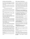
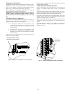
Outdoor Fan Motor
Operation
There are two different types of motors used in the Evolution
2--stage outdoor units. The286B models use aPSC type fan motor,
and the speed does not change between high and low speed
operation.
On 289B models, an ECM fan motor is used to achieve higher
efficiency ratingsof the system. The outdoor unit control energizes
outdoor fan anytime compressor is operating, except for defrost or
low--ambient cooling. The outdoor fan remains energized if a
pressure switch or compressor overload should open. The outdoor
fan motor will continue to operate for one minute after the
compressor shuts off when the outdoor ambient is greater than or
equal to 100°F/37.7°C. This reduces pressure differential for easier
starting on next cycle. On 286B/187B models, the outdoor fan
remains energized during the 1--minute compressor staging time
delay.
On 286B/187B models, the outdoor fan motor is a PSC type. A fan
relay on the control board turns the fan off and on by opening and
closing a high voltage circuit to the motor. It does not change
speeds between low and high stage operation.
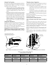
On 289B/180B models, the outdoor fan is an ECM type. The
motor control is continuously powered with high voltage. The
motor speed is determined by electrical pulses provided by the
PWM outputs on the control board. The ECM motor RPM adjusts
to outdoor conditions as described in Table 19. The PWM output
can be measured with a volt meter set to DC volts.
In low ambient cooling (below 55°F/12.7°C), the control board
cycles the fan off and on.
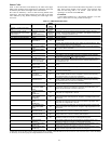
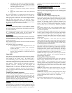
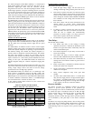
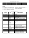
Table 19—Outdoor Fan Motor PWM
Outdoor Temp (DC volts, Tolerance +/-- 2%)
Model
Low Stage
(OAT≤104_F/40_C)
HighStage
(OAT≤104_F/40_C)
Low &High
Stage
(OAT>104_F/40_C)
289BNA036 9.06 10.23 11.90
289BNA048 9.91 11.04 11.90
289BNA060 10.83 11.70 11.90
180BNA024 9.57 10.88 11.90
180BNA036 9.06 10.23 11.90
180BNA048 9.91 11.04 11.90
180BNA060 10.83 11.70 11.90
NOTE: For 289B models in low---ambient cooling, the PWM ou tput for
both high--- and low---stage equals the value for low---stage
operation below 55_F (12.8_C).
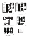
ECM Fan Motor Troubleshooting
If the outdoor fan motor fails to start and run:
S Check the high--voltage supply. The unit need not be
running to check high voltage, but the power must be on.
S If the 230vac is present, use Table 19 to check for proper
control voltage output to the fan motor from the control
board. The control board sends DC voltage signals to the
motor through the terminals labeled PWM1 and PWM2
Set a voltmeter on a DC voltage scale and check across
these terminals.
S First check voltage with the motor disconnected. If no
control voltage is present, check control--board
connections. If connections are good, replace the control
board.
S If voltage is present, reconnect the motor and check
again. Shut down the unit to reconnect the motor and
restart the unit to complete this troubleshooting
procedure. If control voltage is no longer present or
motor fails to respond, check motor connections.
S If connections are good, replace the motor.
Time Delays
The unit time delays include:
S Five minute time delay to start cooling or heating
operation when there is a call from the thermostat or user
interface. To bypass this feature, momentarily short and
release Forced Defrost pins.
S Five minute compressor re--cycle delay on return from a
brown--out condition.
S Two minute time delay to return to standby operation
from last valid communication (with Evolution only).
S One minute time delay of outdoor fan at termination of
cooling mode when outdoor ambient is greater than or
equal to 100_F.
S Fifteen second delay at termination of defrost before the
auxiliary heat (W1) is de--energized.
S Twenty second delay at termination of defrost before the
outdoor fan is energized.
S Thirty second compressor delay when quiet shift
enabled.
S On 226A, 266A, 286B models there is a 1 minute time
delay between staging from low to high and from high to
low capacity. On 289B models there is no delay; the
compressor will change from low to high and from high
to low capacity “on the fly” to meet the demand.
Pressure Switches
The Puronr two--stage air conditioner contains two pressure
switches to prevent system operation if the pressures get
excessively high or low. The air conditioner low pressure switch in
the suction line opens at 50 PSI and closes at 95 PSI. The high
pressure switch opens at 670 PSI and closes at 470 PSI. Both
pressure switch settings are considerably higher than on
comparably sized R--22 units. The high and low pressure switches
can be identified by their pink stripe on the switch’s electrical
wires.
The Puronr two--stage heat pump contains a loss of charge switch
in the suction line on 286B and 289B, and liquid line on 226A and
266A which opens at 23 PSI and closes at 55 PSI. See
troubleshooting section for sequence when a pressure switch trip
occurs.